Table of Contents
Advertisement
Quick Links
Advertisement
Table of Contents

Summary of Contents for Dings DS-OLBD3-FRS4
- Page 1 DS-OLBD3-FRS4 Technical Manual VER 1.0 DS-OLBD3-FRS4 page│1...
- Page 2 DS-OLBD3-FRS4 Product Warranty If a malfunction occurs within one year of purchasing this product due to reasons other than improper operation, • you can send the faulty product back to our company via courier or logistics, and you will enjoy free repair service.
-
Page 3: Table Of Contents
DS-OLBD3-FRS4 Table of Contents 1. Product Overview ……………….…….…………………………………………...…………….…4 Features ..………………………………………………………………………….…………….….4 Parameter ………………..……………………………………………………….…………….….4 Installation Dimension (mm) …...………………………………………………….……………….5 2. Schematic Diagrams and Interface Definitions …………………………………………………………5 Power and Motor Interface Definition CN1 (Power & Motor) ………………….……………..….6 Hall Signal Interface Definition (CN2) ….….…………………………………………………..….6 Control Signal Interface Definition (CN3) ………………………………………………………….6 3. -
Page 4: Product Overview
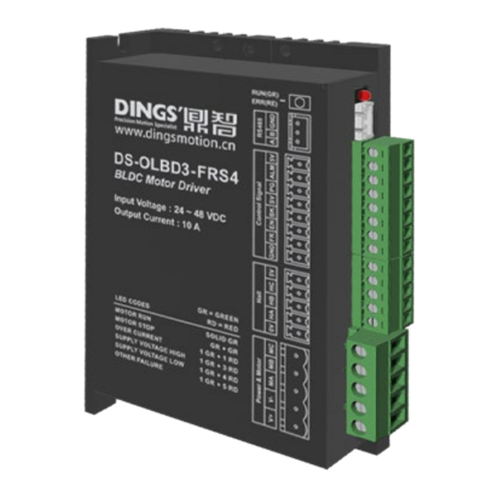
DS-OLBD3-FRS4 1. Product Overview Features Input power : DC 24 - 48V Maximum Peak Current : 30A, duration ≤2 seconds Includes RS-485 debugging, PID speed, and current dual-loop regulators, FOC algorithm Speed Range : 150~10,000 RPM (actual performance depends on motor characteristics) ... -
Page 5: Installation Dimension (Mm)
DS-OLBD3-FRS4 Installation Dimension (Unit : mm) 2. Schematic Diagram and Interface Definitions The 485 debugging port uses a 2.5 pitch 3-pin right-angle termina page│5... -
Page 6: Power And Motor Interface Definition Cn1 (Power & Motor)
DS-OLBD3-FRS4 Power and Motor Interface Definition CN1 (Power & Motor) Terminal number Diagram Pin. Signal name Details Motor phase C Motor phase B Motor phase A Power GND Power VCC Note 1: Power input and motor output use a 5.08 pitch 5-pin terminal. Please connect the power supply and motor correctly, paying attention to the power polarity during wiring. -
Page 7: Led Indicators
DS-OLBD3-FRS4 3. LED Indicators This product has one red-green dual-color LED indicator to display status. Status Display Method: Complete the corresponding number of flashes (0.5 seconds low level, 0.5 seconds high level) for different statuses, complete 2 seconds high level, and then repeat. -
Page 8: Power Supply
DS-OLBD3-FRS4 5. Power Supply Voltage The driver allows for a maximum operating voltage range of 18 ~ 52V DC, with a recommended supply of 24 ~ 48V DC. A voltage stabilizing capacitor can absorb current spikes on the power line, preventing mis protection of the driver. -
Page 9: Enable Signal: En
DS-OLBD3-FRS4 Enable Signal: EN The motor operation and stop can be controlled by inputting a signal to the control terminal EN. When the terminal is connected, the motor runs; otherwise, the motor stops. Using the run/stop terminal to stop the motor results in a natural stop, which is related to the load inertia. -
Page 10: Precautions
DS-OLBD3-FRS4 Wiring diagram Precautions (1) Please correctly connect the power supply and motor, paying attention to the polarity of the power supply. (2) When stripping the wires, do not pre-tin the ends with solder, as this may prevent proper connection. -
Page 11: Motor Connection Method
DS-OLBD3-FRS4 Motor connection method Connection diagram of the driver to the brushless motor Precautions Different motors have different wire colors; refer to the motor's documentation for proper usage. The above motor connection method is typical and for reference only. Please refer to the motor's specification manual for specific wiring methods. - Page 12 DS-OLBD3-FRS4 International Customer Person in Charge : Daniel Jang daniel@dingsmotion.com No. 2850 Luheng Road, Changzhou Economic Development Zone, Jiangsu Province, China +86-519-85177825, 85177826 North America Customer Person in Charge : Nicolas Ha sales@dingsmotionusa.com 335 Cochrane Circle Morgan Hill, CA 95037...
Need help?
Do you have a question about the DS-OLBD3-FRS4 and is the answer not in the manual?
Questions and answers