
Summary of Contents for HOME PILOT premium 1690 10 01
- Page 1 Smart garage door opener premium Translation of the Original Operating and Assembly Manual Item No.: 1690 10 01 (three-section rail) UM G101-2...
-
Page 3: Table Of Contents
Contents Scope of delivery .........4 11.1 Setting end points / setting the upper end point .......25 General view .........5 11.2 Setting the lower end point ....25 Key to symbols .........6 11.3 Carry out reference run for power Safety information .........6 measurement .......26 Proper use... -
Page 4: Scope Of Delivery
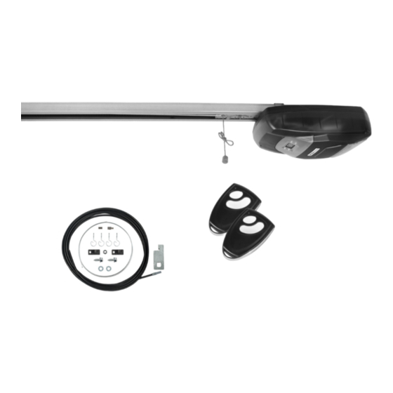
Scope of delivery After unpacking the product, please compare the contents of the package with this list: 1 x Drive 1 x Quick User Guide 2 x Manual transmitters 1 x Door connector, bent 1 x Middle support clip 3 x Fixing bracket 1 x Header bracket 1 x Door bracket 1 x Connector... -
Page 5: General View
General view Legend 1 = Drive, including lighting 7 = Set button (S) 2 = Cover panel (removable) 8 = Display (2 digit) 3 = Manual transmitter 9 = Button for adjustment (+) 4 = Control LED 10 = Button for adjustment (–) 5 = 1 Buttons on the manual transmitter 11 = Programming button (P) 6 = 2 Buttons on the manual transmitter... -
Page 6: Key To Symbols
Key to symbols Risk of fatal electric shock. Important safety information which can lead to property damage if not observed. This sign warns of danger when working on electrical connections, components, etc. It requires that safety Please pay particular attention and carefully follow all precautions be taken to protect the life and health of instructions marked with this symbol. - Page 7 Safety information Important safety instructions. If safety attachments are defective or out of operation there is a risk of injury or damage to It is important for the safety of persons to follow all property. instructions. Save these instructions. ◆ Before commissioning and thereafter once a Incorrect use leads to an increased risk of month, inspect for correct functioning of the safety injury.
-
Page 8: Proper Use
Proper use Use the garage door drive only: A lack of maintenance can lead to personal injury through damage to your garage door drive, the ◆ for opening and closing of approved garage associated safety devices and the garage door doors, see page 10 / 38. -
Page 9: Improper Use
Improper use Using the garage door drive for purposes other The Smart garage door opener premium may than previously mentioned is impermissible. not be used without additional light barriers, see page 34. ◆ This applies especially to: – all manual radio transmitters Incorrectly performed structural alterations –... -
Page 10: Approved Garage Door Types
Approved garage door types ◆ swing out standard up-and-over doors ◆ sectional doors The doors must move smoothly and comply with the regulations of the following standards: EN 12604. Up-and-over Ceiling sectional doors doors 7.1 Inadmissible types of garage door Doors which require tilting and rotating move- Non-swinging tilting ments may not be operated with the Smart... -
Page 11: Functional Description
Functional description The Smart garage door opener premiumis a electronic Smart garage door opener premium garage door driver suitable for use with all standard The Smart garage door opener premium is designed up-and-over and sectional doors (see page 10). for use within a radio network and can be integrated and controlled with a HOMEPILOT Premium gateway Flexible installation options or other HOMEPILOT controllers. -
Page 12: Functional Description / Emergency Release
8.1 Brief description of the convenience functions Lighting Opening speed: The garage door drive has an integrated energy-saving The opening speed can be adjusted in three stages. LED lighting system which is switched on after each It is configurable between 11 cm/s up to 19 cm/s switching impulse and which goes off again automati- (factory setting), see page 30. -
Page 13: Monthly Checks On The Obstacle Detection System (Power Limiting)
8.4 Monthly checks on the obstacle detection system (power limiting) Run the door into the fully open position. Place a 50 mm high object, e. g. a wooden block, in the direction of travel of the door. Close the door by actuating the manual transmitter. -
Page 14: Important Assembly Instructions
10. Important assembly instructions Important instructions for a safe installation. During installation there is a risk of injury due STOP Follow all installation instructions carefully. to the unsecured door falling suddenly. Incorrect installation can lead to serious ◆ During the installation work, ensure that there are injuries. -
Page 15: Required Tools
10.1 Required tools You require the following tools for installation: 10.2 Remove the door locks Remove all vertical and horizontal door locks and catches. NOTE! Keep the old door locks in a safe place. In the event that you should remove the garage door drive, you will have to fit these again in order to restore the original state of the door. -
Page 16: Take Measurements
10.3 Take measurements Measure up and mark the centre of the door. Mark the centre of the door, as shown, on the upper edge of the door, on the door lintel and on the garage ceiling. Determine the distance between the top edge Swing door of the door and the ceiling. -
Page 17: Assembly Of The Rails
10.4 Assembly of the rails NOTE! The Smart garage door opener premium is supplied with three rails: ◆ two end pieces, including a pre-mounted toothed belt. ◆ a middle piece (without toothed belt) with two connectors. Lay the two end pieces with the pre-mounted toothed belt on the ground, with the chain Connector 1 Connector 2... -
Page 18: Connect The Door Drive Housing To The Rail
10.6 Connect the door drive housing to the rail First of all insert the connector (5). IMPORTANT Place the rail (4) with the inboard chain sprocket Ensure that the microswitch (3) is not damaged when (supplied pre-mounted into the rail) over the mounting the rail. -
Page 19: Connect The Door Drive Housing To The Rail (90° Drive Assembling)
10.7 Connect the door drive housing to the rail (90° drive assembling) Alternative installation of the drive transversely to the rail. NOTE! Mortal danger due to electric shock when under- taking any work on the microswitch (3). The microswitch (3) must always be positioned at the end of the rail. -
Page 20: Attachment Of The Drive And Rail
10.8 Attachment of the drive and rail A / B / C / D refers to the following pages Installation on the lintel The installation should preferably be on the lintel, as Installation on this means that the forces encountered can best be the lintel min. -
Page 21: A) Installation Of The Header Bracket (1)
10.9 (A) Installation of the header bracket (1) NOTE! The header bracket (1) must be aligned with the mid- point of the door. Mark out the position of the header bracket (1) and drill the mounting holes (e. g. with a 10 mm masonry drill bit). -
Page 22: C) Installation Of The Door Bracket (8)
10.11 (C) Installation of the door bracket (8) NOTE! ◆ We recommend fixing the door bracket (8) to the door frame if possible. ◆ For plastic or thin-walled wooden doors, ad- ditional cross-beams are necessary in order to avoid damaging the door. In this case, consult your door supplier. -
Page 23: D) Installation Of The Middle Support Clip (13)
10.11 (C) Installation of the door bracket (8) Screw the door bracket (8) tight to the frame with the enclosed self-tapping hexagon screws (8 x 15 mm). Finally, fix the door connector (12) to the door bracket (8) with the enclosed bolt (9). NOTE! ◆... -
Page 24: Important Notes After Installation
10.14 Important notes after installation ◆ Ensure that the mechanism is properly adjusted ◆ Ensure that the drive prevents or stops the opening and that the drive reverses when the door contacts movement when the door is loaded with a mass a 50 mm high object placed on the floor (for drives of 20 kg, fixed centrally on the bottom edge of the incorporating an entrapment protection system... -
Page 25: Setting End Points / Setting The Upper End Point
11.1 Setting end points / setting the upper end point Correct setting order: Carrying out the instructions in the wrong order when setting the end points will result 1. Set upper end point in malfunctions. Be sure to keep to the setting 2. -
Page 26: Carry Out Reference Run For Power Measurement
11.3 Carry out reference run for power measurement During the reference run there is a risk of injury, as the drive develops extremely strong forces. 1. Press "+", the 2. Press "P", 3. The door goes up display shows "3". "3"... -
Page 27: Adjust Power Limiting As Required
11.4 Adjust power limiting as required NOTE! If the power level is too low, the door movement will be impaired, particularly if the mechanical The drive is preset to stage 3 by the supplier. If required structure of the door is not well balanced. (e. -
Page 28: Alarm Setting
11.5 Alarm setting (can also be configured via Premium gateway) If the alarm is switched on, the drive beeps if To end the beeping: the door is open for longer than 10 minutes. Press the door control button to fully close the door. The signal tone is emitted for 30 seconds every 10 minutes. -
Page 29: 2000 Cycle Alarm Setting
11.6 Automatic closing time setting (can also be configured via Premium gateway) 5. Press "+" and select the 6. Press "P" in order to 7. Conclude programming required closing time: store the setting. (see page 32 / Method 2) or proceed with next 1 = 30 s 5 = 150 s setting. -
Page 30: Opening Speed Setting
11.8 Opening speed setting (can also be configured via Premium gateway) With this function you can set the speed of the upwards Configuration of the upwards movement speed is set movement to your individual requirements. in cm/s (centimetres per second). 1. -
Page 31: Back-Jump Function Setting
11.9 Back-jump function setting (can also be configured via Premium gateway) Function After closing, the jump-back function relieves the drive components by briefly moving in the opposite direction (10 mm). 1. Press "P" for approx. 2. Press "+". 3. Press "P", the display is "0". 5 seconds. -
Page 32: Conclude Programming
11.10 Conclude programming The following applies to Smart garage door NOTE! opener premium: ◆ Please note: this concluding step must be The programming must be completed so that you carried out, otherwise the information stored can make settings in the DuoFern network or on the will be lost. -
Page 33: Logging On/Off Manual Transmitters And/Or
12. Logging on/off manual transmitters and/or DuoFern Premium gateway Logging on manual transmitters or DuoFern transmitters: Both manual transmitters are already logged on to the large button on the garage door drive when in the factory. If you want to log on another manual transmitter, or have already logged off a manual transmitter that is included in the scope of supply and want to log it on again, proceed as follows. -
Page 34: Application And Installation Of A Light Barrier
13. Application and installation of a light barrier As an additional safety device you can equip the Functional description for operation with a Smart garage door opener premium garage door drive light barrier with a light barrier (item no. 1699 10 01). If the signal from the light barrier is interrupted while Applies additionally to Smart garage door opener the door is closing, the garage door drive stops and then... -
Page 35: Connection Diagram For Additional Electrical Equipment
14.1 Connection diagram for additional electrical equipment Smart garage door opener premium ( 2 ) ( 3 ) ( 1 ) ( 4 ) 24 V ( 5 ) Legend NOTE! ( 1 ) = main board Remove the respective factory installed bridge before connecting a light barrier or a pass door ( 2 ) = infrared light barrier (optional) contact. -
Page 36: Manual Door Operation
15. Manual door operation In the case of power failure: If you wish to manually operate the door in the There is a risk of injury. The door can fall down event of a power cut, you must pull the emer- uncontrollably when released (e. -
Page 37: Instructions For The User
16. Instructions for the user Notes for use. ◆ When the power is back, you can operate the manual transmitter or the wall panel, and the ◆ Check the drive system to determine whether it emergency release will engage automatically. moves smoothly the first time the garage door drive is used. -
Page 38: Technical Specifications
17. Technical Specifications Power: 150 W Supply voltage: 230V / 50/60Hz Motor: 24 V (DC) Drive type: Toothed belt Standby consumption: - Smart garage door opener premium: < 1 W Tractive force: max. 900 N / 90 kg Speed of door operation: - Opening direction: 11 / 15 / 19 cm / second (adjustable) - Closing direction... -
Page 39: Troubleshooting
18. Troubleshooting Fault Causes Solution 1. The plug is not inserted prop- 1. Plug the mains plug into the The drive does not work. erly. mains socket. 2. The fuse has been tripped. 2. Have the cause checked by a qualified engineer, then reset the fuse. -
Page 40: Simplified Eu Declaration Of Conformity
19. Simplified EU Declaration of Conformity DELTA DORE RADEMACHER GmbH hereby declares that included with the product and is kept on file by the the Smart garage door opener premium complies with manufacturer.s. the Directives 2006/42/EC (Machinery directive) and DELTA DORE RADEMACHER GmbH 2014/53/EU (Radio Equipment Directive). - Page 42 DELTA DORE RADEMACHER GmbH Buschkamp 7 46414 Rhede (Germany)
Need help?
Do you have a question about the premium 1690 10 01 and is the answer not in the manual?
Questions and answers