Advertisement
Quick Links
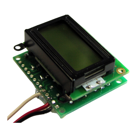
Construction Manual &
Analog Digital Radiation Meter
The Analog Digital Radiation Meter counts the pulse output of a standard
analog Geiger counter to provide a visual readout of the CPS, approximate
radiation level (imperial/metric) and analog radiation field strength meter.
Features:
·
7-12VDC or 5VDC power supply input
·
Counts TTL pulses from Analog Geiger Counter
·
Outputs Digital Counts Per Second (CPS) value
·
Outputs radiation level (imperial / metric)
·
LCD Backlight
·
Available as a kit or assembled
Images Scientific Instruments Inc.
109 Woods of Arden Road
Staten Island NY 10312
718.966.3694 Tel
718.966.3695 Fax
www.imagesco.com
Users Guide
Model ADM-01
Advertisement

Summary of Contents for Images Scientific Instruments ADM-01
- Page 1 Images Scientific Instruments Inc. 109 Woods of Arden Road Staten Island NY 10312 718.966.3694 Tel 718.966.3695 Fax www.imagesco.com Construction Manual & Users Guide Model ADM-01 Analog Digital Radiation Meter The Analog Digital Radiation Meter counts the pulse output of a standard analog Geiger counter to provide a visual readout of the CPS, approximate radiation level (imperial/metric) and analog radiation field strength meter.
- Page 2 Mounting the Meter..... . .8 ADM-01 Parts List......8 Wiring Diagrams.
-
Page 3: Powering The Unit
Geiger counter. The default display will provide readings in CPS and mR/ The ADM-01 has two switches on the right hand side of the board. The bottom switch is the power switch. The top switch allows you to turn the backlight on the LCD on and off. - Page 4 /male headers or 22ga. wires depending upon your application. In this example we are connecting to the ADM-01 using wires. In our example we are powering the ADM-01 board using a 5 volt power sup- ply (red wire), Ground (GND black wire) and the B0 (white wire) soldered on the PCB as shown below in figure 4.
- Page 5 Figure 5...
- Page 6 Construction Figure 5 shows the schematic for the Analog Digital Radiation Meter (ADM- 01). Figure 6 is the blank PCB. All components are mounted and soldered to the top silkscreened side of the board unless otherwise noted. Figure 6 To begin mount and solder the 5-pin 10K resistor pack (R1). Pin 5 (last pin when reading the text on the resistor) should go in the top hole of R1 on the PCB.
- Page 7 Be sure to line up the notch in the chip with the notch in the socket. You need to think about how you want to connect the ADM-01 to your circuit and what power supply you want to use. The ADM-01 is a versatile develop- ment board for the 16F88 PIC microcontroller.
-
Page 8: Mounting The Meter
*You are now ready to connect the Analog Digital Radiation meter to an ana- log Geiger counter. Connect the white wire to the pulse output of the Geiger counter. Make sure both the Geiger counter and ADM-01 meter share a com- mon ground. Various wiring diagrams are included on the following pages. - Page 9 Wiring Options for ADM-01 Analog / Digital Meter The following images show a variety of wiring options available for our Analog Digital Meter. Figure 10 Figure 11 Figure 10 outlines wiring connec- tions for supplying the unit with 5V power. Figure 11 outlines the wiring for 9V.
- Page 10 Wiring Options for ADM-01 Analog / Digital Meter The following images shows power and pulse connections to GCK/GCA-01. Figure 14...
- Page 11 Wiring Options for ADM-01 Analog / Digital Meter The following images shows power and pulse connections to GCK-02. Figure 15...
Need help?
Do you have a question about the ADM-01 and is the answer not in the manual?
Questions and answers