
Subscribe to Our Youtube Channel
Summary of Contents for Miyachi UNIFLOW 3
- Page 1 OPERATOR MANUAL 990-894 Revision H November 2013 ® UNIFLOW PULSED HEAT CONTROL MODEL NUMBERS 1-298-01 1-298-01-01 1-298-01-02 1-298-01-03...
-
Page 2: Revision Record
Copyright © 2010, 2013 Miyachi America Corporation The engineering designs, drawings and data contained herein are the proprietary work of Miyachi America Corporation and may not be reproduced, copied, exhibited or otherwise used without the written authorization of Miyachi America Corporation. -
Page 3: Table Of Contents
CONTENTS Page Revision Record ............................ii Contents .............................. iii Contact Us .............................. vi Safety Precautions ............................ vii Chapter 1. Description Section I: Features ..........................1-1 Overview ............................1-1 Control Models ..........................1-2 Heads, Thermodes and Accessories ....................1-2 Section II: Controls and Indicators ......................1-3 Front Panel ............................ -
Page 4: Contents
CONTENTS (Continued) Page Chapter 3. Using Programming Functions Overview ............................3-1 Front Panel Display ..........................3-1 Screen Navigation and Menu Selection ....................3-1 Run Mode ............................3-2 Setup Mode ............................3-2 Graph Key ............................3-3 Graph Schedule Profile ........................3-3 Process Cycles ............................ - Page 5 Page Buzzer Loudness ..........................3-17 End of Cycle Buzzer ........................3-18 Set Output Relays .......................... 3-18 Preheat ............................ 3-18 Reflow ............................ 3-18 Baseheat ..........................3-18 Alarm ............................3-18 Clean Thermode ........................3-19 Replace Thermode ........................3-19 End Of Reflow ........................3-19 Head Is Up ..........................
- Page 6 CONTENTS (Continued) Page Section III: Graph and Data Screen Descriptions ................... 4-3 Graph Screen Description ........................ 4-3 Graph Schedule Profile ........................4-3 Graph Actual Temperature and Envelope Limits ................4-3 Data Screen Description ........................4-5 Data Screen Abbreviations and Time calculations ................4-6 Section IV: Process Cycle Parameters ....................
-
Page 7: Contact Us
The contents of this manual are subject to change without notice. If you have any questions, or find any errors or omissions in this manual, please contact us. Miyachi America is not responsible for any losses due to improper use of this product. -
Page 8: Safety Precautions
Use the appropriate tools for terminating the connecting cables, being careful not to nick the wire conductors. Do not modify the Control without prior written approval from Miyachi America. HIGH VOLTAGE is used in the operation of this equipment. - Page 9 Before using this equipment, read the SAFETY PRECAUTIONS carefully to understand the correct usage of the equipment. x These precautions are given for safe use of the equipment and for prevention of injury to operators or others. x Be sure to read each of the instructions, as they are all important for safe operation.
- Page 10 Stop operation if any trouble occurs. If you detect a burning smell, abnormal sounds, abnormal heat, smoke, etc., turn power OFF immediately to prevent fire or electric shock. Contact Miyachi America or your distributor for help. People with pacemakers MUST stay away from the Control.
- Page 11 CAUTION Apply the specified source voltage. Applying the wrong voltage can cause fire and electrical shock. Keep water and water containers away from the Control. Water spilled on the Control can cause a short circuit, electrical shock, or fire. Use proper tools (wire strippers, pressure wire connectors, etc.) for terminations of the connecting cables.
- Page 12 ® UNIFLOW 3 PULSED HEAT CONTROL 990-894...
- Page 13 ® UNIFLOW 3 PULSED HEAT CONTROL 990-894 xiii...
-
Page 15: Chapter 1. Description Section I: Features
Control. This manual describes the most common or “typical” components and options. If you have questions about custom items in your Control that are not covered in this manual, contact Miyachi America using the phone, e-mail, or mailing information on the... -
Page 16: Control Models
4” (100 mm) long Heads, Thermodes and Accessories For details of solder reflow and heat seal heads, thermodes and accessories available from Miyachi America, please contact Miyachi America using the phone, e-mail, or mailing information in the Foreword of this manual. -
Page 17: Section Ii: Controls And Indicators
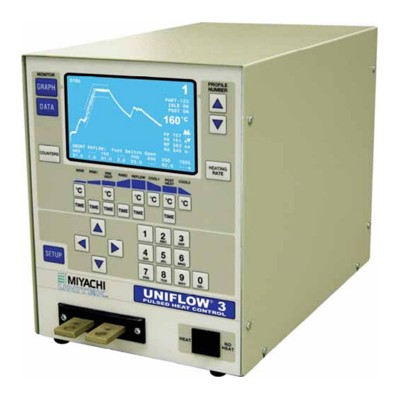
CHAPTER 1: DESCRIPTION Section II: Controls and Indicators Front Panel Display (LCD) The LCD on the front panel displays both graphic and alphanumeric data depending on the function chosen by the Operator. NOTE: These screens, their functions and displays are described in Chapter 3, Using Programming Functions and Chapter 4, Operation. -
Page 18: Numerical Keypad
CHAPTER 1: DESCRIPTION Numerical Keypad The keypad allows you to edit the numeric values of the display screens. The keypad also allows you to enter in the alphanumeric schedule reference which is displayed on the graphic screen Cursor Keys The cursor keys allow you to move the editing cursor up, down and sideways. You use the (Up) and (Down) keys to select multiple pages in a single... -
Page 19: Data Key
CHAPTER 1: DESCRIPTION DATA Key key brings up the data screen to the display. DATA The data screen reports the most recent heat cycle parameters in numerical format: time, temperature, duty cycle, and counter status (when enabled). You may initiate the cycle while the HEAT screen (rather than the graphic... -
Page 20: Data Edit Keys
CHAPTER 1: DESCRIPTION DATA EDIT Keys The data edit keys allow you to edit the time and temperature parameters of the heat profile on the graphic display. The keys BASE RISE1 PREHEAT RISE2 REFLOW, COOL1, POSTHEAT COOL2 are vertically aligned with the profile heating states as displayed on the graphic screen. These keys are only active when the graphic screen is displayed. -
Page 21: Setup Key
CHAPTER 1: DESCRIPTION SETUP Key This key brings up the screen. SETUP MENU screen provides a menu of SETUP MENU < SETUP MENU > operating characteristics for the Control. HARDWARE SETUP COMMUNICATIONS REFLOW SETUP SYSTEM SECURITY COPY PROFILE SET TO DEFAULTS LANGUAGE I/O STATUS Number... -
Page 23: Chapter 2. Installation And Setup Section I: Planning For Installation
CHAPTER 2 INSTALLATION AND SETUP Section I: Planning for Installation Space Requirements Dimensions (including all projections from the housing, but excluding cabling): Weight: 4 KVA models: 60 pounds (27.2 kg) 2 KVA models: 48 pounds (21.8 kg) Install the Control in a well-ventilated area that is free from excessive dust, acids, corrosive gases, salt and moisture. -
Page 24: Section Ii: Connections To External Equipment
CHAPTER 2: INSTALLATION AND SETUP Section II: Connections To External Equipment Overview All connections, other than the transformer cable connections, between the Control and external equipment are made through the rear panel. The transformer cable connections from the reflow soldering or heat seal head are made at the transformer cable terminals on the front panel. NOTE: If you require compressed air, cover gas, and cooling water service for the reflow soldering or heat seal head, please refer to the head manufacturer’s user’s manual for service specifications. -
Page 25: Input Power Connections
Input Power Connections CAUTION Be sure that the source power is appropriate for your Uniflow 3 Control model. Connect the Control power cable to a single-phase, 50/60Hz power source. The nominal voltage range for each model is set at the factory: either 100 to 120 VAC, or 200 to 240 VAC. - Page 26 CHAPTER 2: INSTALLATION AND SETUP Connect the two transformer cables from the head to the transformer terminals on the Control front panel. Transformer Terminal Dimensions ® UNIFLOW 3 PULSED HEAT CONTROL 990-894...
-
Page 27: Section Iii: Equipment Setup
CHAPTER 2: INSTALLATION AND SETUP Section III: Equipment Setup Force Fired, Mechanically Actuated Head 1. Adjust the reflow soldering head force adjustment knob to produce 5 units of force, as displayed on the force indicator index. Connect the reflow soldering head firing switch cable connector to the Control firing switch cable connector. -
Page 28: Force Fired, Air Actuated Head
CHAPTER 2: INSTALLATION AND SETUP Set the circuit breaker on the rear panel of the Control to the ON position. The default graphic screen will display. You will use this screen to enter heating parameters. Force Fired, Air Actuated Head 1. - Page 29 CHAPTER 2: INSTALLATION AND SETUP NOTE: If Connector EMO, Pins 1 and 2, on the rear panel are not shorted, either by an EMO switch or the jumper plug, this screen will include the message: NOTE: EMO JUMPER NOT INSTALLED Using the air-head manufacturer’s user manual for reference, connect the head air valve solenoid cable connector to the Control connector.
- Page 30 CHAPTER 2: INSTALLATION AND SETUP 15. Adjust the head down speed control knob and repeat Step 14 until the thermode descends smoothly. 16. Press the foot switch to actuate the first level and set the thermode on the parts. Release the foot switch and verify that thermode does not impact during retraction.
-
Page 31: Chapter 3. Using Programming Functions
CHAPTER 3 USING PROGRAMMING FUNCTIONS Overview To ensure accurate, consistent soldering, the Control delivers extremely precise pulses of energy to the reflow head. Each pulse is comprised of time and energy values pre-programmed by the user. Chapter 1, Description told you where the Controls and Indicators are located. This chapter describes how to use them in order to program the precise temperature profiles needed for reflow soldering, heat sealing or other processes. -
Page 32: Run Mode
® CHAPTER 3: USING UNIFLOW 3 PROGRAMMING FUNCTIONS In general, there are three kinds of instructions on the bottom line of the screen. For and example, refer to the screen: Schedule Setup Page 1 of 2 The instruction on the left side of the screen briefly describes the appropriate response for the options on the current screen. - Page 33 ® CHAPTER 3: USING UNIFLOW 3 PROGRAMMING FUNCTIONS Graph Key Pressing the key when any screen is displayed except for the Graph and GRAPH Schedule Setup Screens, will change the display to the screen. Pressing GRAPH key when the Graph or Schedule Setup Screens are displayed will GRAPH rotate the screen display through the and two...
-
Page 34: Base
® CHAPTER 3: USING UNIFLOW 3 PROGRAMMING FUNCTIONS The user can include a process cycle in a Profile by assigning the desired process cycle a time of greater than 0 seconds. The Control requires that every Profile have at least one process cycle, Reflow with a time of at least 0.1 seconds. -
Page 35: Cool1
® CHAPTER 3: USING UNIFLOW 3 PROGRAMMING FUNCTIONS NOTE: The temperature will always be higher than the actual melting point of the solder or heat Reflow seal adhesives due to heat losses in both the thermode and parts. is shown as having a time length of 3.0 seconds and a set-point temperature of 350qC. Time can Reflow be set for 0.1 to 99.9 seconds. -
Page 36: Schedule Setup Parameters
® CHAPTER 3: USING UNIFLOW 3 PROGRAMMING FUNCTIONS Schedule Setup Parameters screens are accessed Schedule Setup < SCHEDULE SETUP, Page 1 of 2 > by pressing the key. GRAPH ENABLE PEAK AND AVG LIMITS PREHT PEAK TIME DELAY 01.0 SEC Pressing the key when the Graph GRAPH... - Page 37 ® CHAPTER 3: USING UNIFLOW 3 PROGRAMMING FUNCTIONS PREHT PEAK HI TEMP LIMIT +030 Press the through keys to edit the high < and low limits for the peak and average temperatures. The number entered will be the difference between the profile set After edit Page to accept new value temperature and the limit.
- Page 38 ® CHAPTER 3: USING UNIFLOW 3 PROGRAMMING FUNCTIONS RISE1 TIME DELAY Press the key to set the RISE1 or These parameters allow RISE2 TIME Delays. the user to set the envelope to begin at some After edit Page to accept new value point after the start of Rise1 or Rise2.
- Page 39 ® CHAPTER 3: USING UNIFLOW 3 PROGRAMMING FUNCTIONS Press the key to set the time length of the x axis of the Graph. The GRAPH GRAPH TIME SPAN can be set from 0 to 600 TIME SPAN seconds and can be changed after a After edit Page to accept new value reflow if an expanded or close-up view is...
-
Page 40: Data Key
® CHAPTER 3: USING UNIFLOW 3 PROGRAMMING FUNCTIONS > Press the key to enter the REFERENCE TEXT This field will accept any alphanumeric character, “- “, or space. The numbers and letters are entered via the numeric keypad. One press will enter a number, a second, third or fourth press of the same key will enter a letter in the sequence printed on the key for each number. -
Page 41: Profile Number Keys
® CHAPTER 3: USING UNIFLOW 3 PROGRAMMING FUNCTIONS PROFILE NUMBER Keys With the graphics screen on the display, these keys will increment/decrement the heat profile number on the graphics screen. With the data screen on the display, pressing either key returns the graphics screen to the display; PROFILE NUMBER the keys will then increment/decrement the profile number on the screen. -
Page 42: Replace Counter
® CHAPTER 3: USING UNIFLOW 3 PROGRAMMING FUNCTIONS < CLEAN COUNTER SETUP > Pressing will toggle CLEAN COUNTER CLEAN COUNTER between will activate CLEAN COUNTER ACTION STOP this feature and will de-activate it. EDIT CLEAN COUNTER +000010 Pressing will toggle CLEAN COUNTER between ACTION... -
Page 43: Data Edit Keys
® CHAPTER 3: USING UNIFLOW 3 PROGRAMMING FUNCTIONS DATA EDIT Keys The data edit keys allow you to edit the time and temperature parameters of the heat profile on the graphic display. The Temperature and Time keys for each process segment are vertically aligned with the profile heating states as displayed on the graphic screen. -
Page 44: Saving Changed Values
® CHAPTER 3: USING UNIFLOW 3 PROGRAMMING FUNCTIONS Saving Changed Values When you change values, they are saved in the Control’s flash memory (“flash” for short) when the , or screens are used. GRAPH DATA COUNTERS HEATING RATE SETUP CAUTION: Before you power down, go to one or more of the screens above and verify your changes. If you do not use one of these screens before powering down, your changes will not be saved. - Page 45 ® CHAPTER 3: USING UNIFLOW 3 PROGRAMMING FUNCTIONS Coarse Heating Rate Thermode Family Series Very Slow Slow Medium Fast 17BM, up to 10 mm (0.37 in.) 17BM, 10 to 30 mm (0.37 to 1.2 in.) 17BW, 30 to 60 mm (1.2 to 2.4 in.) 17BW, 60 to 100 mm (2.4 to 4.0 in.)* 17F, up to 10 mm (0.37 in.) 17F, 10 to 30 mm (0.37 to 1.2 in.)
-
Page 46: Setup Key
® CHAPTER 3: USING UNIFLOW 3 PROGRAMMING FUNCTIONS SETUP Key This key brings up the screen. SETUP MENU screen provides a SETUP MENU < SETUP MENU > menu of operating characteristics for the HARDWARE SETUP Control. COMMUNICATIONS REFLOW SETUP SYSTEM SECURITY COPY PROFILE SET TO DEFAULTS LANGUAGE... -
Page 47: Footswitch Response Mode
® CHAPTER 3: USING UNIFLOW 3 PROGRAMMING FUNCTIONS The solder cool valve will also activate at the end of and de-activate when the thermode POSTHEAT temperature reaches either the temperature which ever is lower. The COOL2, PREHEAT, or BASE solder cool valve is used to direct the cool air onto the thermode to force it to cool faster. The solder cool valve supplies a connector-selectable 24 VAC or +24 VDC signal for controlling a user supplied air solenoid valve. -
Page 48: End Of Cycle Buzzer
® CHAPTER 3: USING UNIFLOW 3 PROGRAMMING FUNCTIONS END OF CYCLE BUZZER Press the key to toggle between for the end of cycle buzzer. When you select the option, a buzzer will sound when the actual thermode temperature reaches the temperature setting. -
Page 49: Clean Thermode
: Relay is when head is retracted HEAD IS UP NC/NO : Relay is when Uniflow 3 Control is ready for reflow operation SYSTEM READY NC/NO : Relay is during baseheat, rise1, preheat,rise2, reflow and postheat process cycle HEAT ON NC/NO <... -
Page 50: Rs232/485 Select
® CHAPTER 3: USING UNIFLOW 3 PROGRAMMING FUNCTIONS RS232/485 SELECT Pressing the 3 key will alternately select either RS232 or RS485 communications. Default value is RS232. BAUD RATE key on the menu COMMUNICATION < BAUD RATE > brings up the screen. -
Page 51: Set Idle Temperature On/Off
® CHAPTER 3: USING UNIFLOW 3 PROGRAMMING FUNCTIONS SET IDLE TEMPERATURE ON/OFF Press the key to toggle between < REFLOW TEMPERATURE SETUP > . Selecting enables the Idle IDLE TEMPERATURE IS Temperature value in the Profile. The SET SAFETY TIMER 10 SEC Idle temperature is set on the Schedule SET RELEASE TIMER... -
Page 52: Max. Temperature Limit
® CHAPTER 3: USING UNIFLOW 3 PROGRAMMING FUNCTIONS MAX. TEMPERATURE LIMIT Press the 4 key to bring up the < MAX TEMPERATURE LIMIT > screen. With this TEMPERATURE LIMIT MAX TEMPERATURE LIMIT screen, you may set the maximum temperature required for an application. The default temperature of 600qC is After edit Page to accept new value... -
Page 53: Profile Lock
® CHAPTER 3: USING UNIFLOW 3 PROGRAMMING FUNCTIONS Once you have returned to the graph or data screens, you can only unlock system security by entering the password again via the screen. CHANGE PASSWORD inhibits the user from modifying any reflow parameters and from selecting different PROFILE LOCK profile schedules. -
Page 54: Language
® CHAPTER 3: USING UNIFLOW 3 PROGRAMMING FUNCTIONS LANGUAGE Press the key to bring up the < LANGUAGE > screen. With this screen, you LANGUAGE may select the screen language to either LANGUAGE ENGLISH SPRACHE DEUTSCH English by pressing the key or to German by pressing the key. -
Page 55: Chapter 4. Operating Instructions
CHAPTER 4 OPERATING INSTRUCTIONS Section I: Before You Start Preparation Before operating the Control: You must be familiar with the principles of reflow soldering. You must be familiar with the location and function of Controls and Indicators. For more information, see Chapter 1, Description. Verify that all equipment has been connected properly. -
Page 56: Section Ii: Power Up
CHAPTER 4: OPERATING INSTRUCTIONS Section II: Power Up Powering Up To turn the Control power ON, set the circuit breaker/power switch on the rear panel to the ON position. After one introductory screen is displayed, the GRAPH screen will display with the message. -
Page 57: Section Iii: Graph And Data Screen Descriptions
CHAPTER 4: OPERATING INSTRUCTIONS Section III: Graph and Data Screen Descriptions Graph Screen Description Graph Schedule Profile A graphical representation of the programmed temperature profile is displayed in the upper left section of the Screen. GRAPH A thin solid line represents the programmed temperature profile with temperature on the Y axis and time on the X axis. - Page 58 CHAPTER 4: OPERATING INSTRUCTIONS GRAPH Screen Detail #1 The five lines of information in the upper right corner are: Profile Number 10 alpha-numeric character user settable reference for selected profile will be displayed is IDLE ON the Idle temperature was set to on in Reflow Setup schedule.
-
Page 59: Data Screen Description
CHAPTER 4: OPERATING INSTRUCTIONS GRAPH Screen Detail #3 The three lines at the bottom of the screen are: The lowest line indicates the time length of each process cycle of the current Profile. The second line from the bottom of the screen indicates the temperature for each Close-UP View process cycle of the current... -
Page 60: Data Screen Abbreviations And Time Calculations
CHAPTER 4: OPERATING INSTRUCTIONS Data Screen Abbreviations and Time calculations Abbreviation Time Calculation Baseheat Initiation of to end of process Baseheat time. End of to when the actual temperature reaches 87.5% of the temperature Base Preheat Rise1 setting in the Profile.. From the point where reached 87.5% of the temperature setting to end of... -
Page 61: Section Iv: Process Cycle Parameters
CHAPTER 4: OPERATING INSTRUCTIONS Section IV: Process Cycle Parameters Temperature Setting Ranges: Idle......................25° to 100°C Base ....................25° to 300°C Preheat ....................60° to 500°C Reflow (default) .................60° to 600°C Reflow (extended mode operation) ...........60° to 999°C Cool1 ....................25° to 300°C Postheat ....................25° to 600°C Cool2 ....................25°... -
Page 62: Section V: Operating Instructions
CHAPTER 4: OPERATING INSTRUCTIONS Section V: Operating Instructions When the message displays after Power Up, the Control is ready for operation using SYSTEM READY either of the following options: Pre-Defined Reflow Profiles. For your convenience, you may quickly select a profile stored in the Control that has been pre-defined for your most common reflow applications. - Page 63 CHAPTER 4: OPERATING INSTRUCTIONS BASE qC Press the key to select the temperature value for editing. BASE NOTE: The temperature BASE value will be highlighted when it is selected. In this example the temperature value is BASE as shown in the bottom left corner of the screen on the right.
- Page 64 CHAPTER 4: OPERATING INSTRUCTIONS REFLOW qC Press the key to select the temperature value for editing. Use the keypad REFLOW to enter a temperature 250qC, then press the key. 9. Press the key to select the time field for editing. Use the keypad to REFLOW TIME REFLOW enter a...
-
Page 65: Chapter 5. Maintenance Section I. Before You Start
Turn power to the Control OFF before starting maintenance work. Tag (and preferably lock) the switch so that power is not accidentally restored. Do not modify the Control without prior written approval from Miyachi Corporation. Use the appropriate tools for terminating the connecting cables, being careful not to nick the wire conductors. - Page 66 CHAPTER 5: MAINTENANCE Message Description time has not been reached yet. Reflow Time The Control is operating in the Reflow Time period Rise1 Time The Control is operating in the Rise1 Time period Rise2 Time The Control is operating in the Rise2 Time period System Ready The Control is ready to begin a reflow process cycle.
-
Page 67: Section Ii. Troubleshooting
CHAPTER 5: MAINTENANCE Section II. Troubleshooting Alarm Message Description Corrective Action When the FOOTSWITCH RESPONSE MODE is set to ABORT, ABORT REFLOW: Firing Maintain firing switch closure for releasing the firing switch connection Switch Open required time. aborts the reflow and produces this message.* When the FOOTSWITCH ABORT REFLOW: Foot... - Page 68 CHAPTER 5: MAINTENANCE Alarm Message Description Corrective Action Reflow soldering head will not activate without installing a CE required Emergency Stop switch or jumper wire. The system has detected a potentially hazardous condition necessitating operator intervention. Normal reflow operation is inhibited. NOTE: When the Emergency Circuit is opened, the buzzer will sound, the Alarm relay state will become active,...
- Page 69 CHAPTER 5: MAINTENANCE Alarm Message Description Corrective Action NOTE (Continued): User applies a signal at J4A-7 on the Control back panel to reset the ALARM relay state. The User presses the Up Arrow EMERGENCY STOP Key, GRAPH, DATA or any other ACTIVATED (Continued) Function Key on the front panel.
- Page 70 CHAPTER 5: MAINTENANCE Alarm Message Description Corrective Action An increase in power did not result in Make sure that the Thermocouple is OVER POWER ALARM an increase in temperature. This – plugged in, is undamaged, and is still Check TC (thermocouple), message is displayed for Over Power bonded to the Thermode.
- Page 71 CHAPTER 5: MAINTENANCE Alarm Message Description Corrective Action WARNING! HEAT Heat switch is pushed to No Heat so Push Heat switch to Heat position to SWITCH IN NO HEAT heat will not be applied to thermode apply heat to thermode. POSITION Once this message is displayed, the front panel keypad will not be operable until the time of the user set Graph Time Span has transpired and the thermode temperature is below the applicable Cool1, Cool2, Preheat, and Base temperature...
-
Page 72: Section Iii. Maintenance
CHAPTER 5: MAINTENANCE Section III. Maintenance Thermode Maintenance When a heat profile has been suitable for a particular application over many bonds, but poor quality bonds are now resulting, thermode surface deterioration could be the problem. If you need to increase heat period temperature and time to maintain the same bond quality, the thermode surface is probably coated with heavy flux, adhesive or polyimide ribbon flex cable residue. -
Page 73: Chapter 6. Calibration
CHAPTER 6 CALIBRATION Overview This pulsed heat control equipment does not use internal calibration adjustments. High precision temperature capturing electronics is used which does not drift with age or use. This procedure allows the user to verify the calibration condition of the unit. Any out-of-calibration condition can only be caused by an internal part failure on the main board and can only be remedied by replacing the broken part. -
Page 75: Appendix A. Technical Specifications
APPENDIX A TECHNICAL SPECIFICATIONS Electrical Mains AC Voltage Ranges: Model 1-298-01 ..................... 90 to 132 VAC Models 1-298-01-01, 1-298-01-02, 1-298-01-03 ..........180 to 264 VAC Line Frequency .........................50 or 60 Hz Line Phase ..........................Single Input Circuit Breaker Rating .....................15 A Power Cord Connection .............European CE Harmonized Wiring Code, or NEMA Wiring Code Environment... - Page 76 APPENDIX A: TECHNICAL SPECIFICATIONS Performance User Programmable Heat Profiles ....................15 Flash Memory Thermocouple Inputs (automatic recognition): Type E ..................For temperatures below 900qC Type J ................... For temperatures below 750qC Type K ..................For temperatures below 1000qC Thermocouple Calibration Input Standards ........User provided NIST standard (separate calibration required for each thermocouple type) Temperature Control Accuracy:...
- Page 77 APPENDIX A: TECHNICAL SPECIFICATIONS Switched Input Electrical Requirements ( Continued Heat Initiation Sensor ............. Heat force or Uniflow 3 head down sensor for initiating thermode heating No Heat Switch......................Heat only inhibit Emergency Stop (CE Requirement)............. SPST switch open to remove...
- Page 78 Head Is Up ............... On/Off when head is retracted System Ready .……………On/Off when Uniflow 3 Control is ready for reflow operation Heat On .... On/Off during baseheat, rise1, preheat,rise2, reflow and postheat process cycle Idle ....................On/Off if idle temperature On...
- Page 79 APPENDIX B ELECTRICAL AND DATA CONNECTIONS RS-232 Connections #1 --.No Connection #6 – Data Terminal Request #2 --. RS-232 Transmit #7 – Clear To Send #3 – RS-232 Receive #8 – Request To Send #4 – Data Set Ready #9 – Ring Indicator #5 –...
-
Page 80: Appendix B. Electrical And Data Connectors
APPENDIX B: ELECTRICAL AND DATA CONNECTIONS Negative/Positive Logic Operation Your Control is factory-configured for negative logic, active low. That is, when an input terminal is unterminated, an internal resistor pulls the input terminal to a positive voltage and the input terminal is considered to be inactive. - Page 81 APPENDIX B: ELECTRICAL AND DATA CONNECTIONS Control Input Interface NOTE: The may be connected to a PLC or other interface in the configurations Control Input Interface shown on pages B-4 £ B-9. ® UNIFLOW 3 PULSED HEAT CONTROL 990-894...
- Page 82 APPENDIX B: ELECTRICAL AND DATA CONNECTIONS Switch Contact Input (Internal Power) ® UNIFLOW 3 PULSED HEAT CONTROL 990-894...
- Page 83 APPENDIX B: ELECTRICAL AND DATA CONNECTIONS Switch Contact Input (External Power) ® UNIFLOW 3 PULSED HEAT CONTROL 990-894...
- Page 84 APPENDIX B: ELECTRICAL AND DATA CONNECTIONS Common Negative Input (Internal Power) ® UNIFLOW 3 PULSED HEAT CONTROL 990-894...
- Page 85 APPENDIX B: ELECTRICAL AND DATA CONNECTIONS Common Negative Input (External Power) ® UNIFLOW 3 PULSED HEAT CONTROL 990-894...
- Page 86 APPENDIX B: ELECTRICAL AND DATA CONNECTIONS Common Positive Input (Internal Power) ® UNIFLOW 3 PULSED HEAT CONTROL 990-894...
- Page 87 APPENDIX B: ELECTRICAL AND DATA CONNECTIONS Common Positive Input (External Power) ® UNIFLOW 3 PULSED HEAT CONTROL 990-894...
- Page 88 APPENDIX B: ELECTRICAL AND DATA CONNECTIONS Force Valve Drive Connections Valve Driver Outputs 24 VAC/VDC, 0.3 A max Output Rating: Output Voltage Selection: AC or DC 24 volt output power is selectable by connecting the proper plug as shown on the next page. NOTES: For AIR HEAD VALVE operation either (1) jumper HEAD VALVE CONNECTOR pin 2 and pin 4 or (2) jumper J4A pin 6 (AIR HEAD) to VALVE DRIVER COMMON or <0V OUT>...
- Page 89 APPENDIX B: ELECTRICAL AND DATA CONNECTIONS Output Voltage Selection: (Continued) To change from 24VAC output power to 24 VDC output power , unplug the white AC plug from the connector shown below and plug in the white DC plug. Timing: The force valve actuates when the first level of the foot switch is closed.
- Page 90 End of Reflow..... On/Off when COOL1 is reached if no Postheat cycle, otherwise COOL2 Head Is Up..................On/Off when head is retracted System Ready ...……………On/Off when Uniflow 3 Control is ready for reflow operation Heat On .... On/Off during baseheat, rise1, preheat,rise2, reflow and postheat process cycle Idle ....................On/Off if idle temperature On...
- Page 91 APPENDIX B: ELECTRICAL AND DATA CONNECTIONS Relay State Timing (Without Postheat process cycle) Relay State Timing (With Postheat process cycle) ® UNIFLOW 3 PULSED HEAT CONTROL 990-894 B-13...
- Page 92 APPENDIX B: ELECTRICAL AND DATA CONNECTIONS ® UNIFLOW 3 PULSED HEAT CONTROL B-14 990-894...
- Page 93 APPENDIX B: ELECTRICAL AND DATA CONNECTIONS Remote Selection with Switches or Opto-Couplers You may use either a 1-level or 2-level foot switch with the Control. Foot Switch Inputs: When using a 1-level foot switch, you must jumper the two-level inputs together so that the two levels operate as an OR-function, as shown in the Figure above.
- Page 94 APPENDIX B: ELECTRICAL AND DATA CONNECTIONS Automation Control Inputs Connections 0 or 24 VDC Input Signal: All Profiles must be entered and saved in the Control memory Remote Profile Inputs: locally (from the Front Panel). Once they are saved, they can be recalled prior to initiating the Reflow process by placing a binary value on the four lines.
- Page 95 APPENDIX B: ELECTRICAL AND DATA CONNECTIONS Operator Initiation Switch and Firing Switch Inputs 0 or 24 VDC Input Signal: ® UNIFLOW 3 PULSED HEAT CONTROL 990-894 B-17...
- Page 96 APPENDIX B: ELECTRICAL AND DATA CONNECTIONS EMERGENCY STOP Input 24 VDC at 2 Amps minimum Switch Rating: Normally closed pushbutton Type of Switch: When the switch is pressed, it removes 24-volt Timing: EMERGENCY STOP power from the reflow head, causing it to retract immediately. Manual Alarm Reset Input Signal : 0 to 24 VDC...
-
Page 97: Appendix Csystem Timing
APPENDIX C SYSTEM TIMING No Post-Heat Pulse = Cool1 Temperature Setpoint COOL1 ® UNIFLOW 3 PULSED HEAT CONTROL 990-894... - Page 98 APPENDIX C: SYSTEM TIMING Process With Post-Heat Pulse = Cool2 Temperature Setpoint COOL2 ® UNIFLOW 3 PULSED HEAT CONTROL 990-894...
- Page 99 APPENDIX D COMMUNICATION CODES Section I. Command Format COMMAND KEYWORDS: BOLD. italics. VARIABLE: {enclosed in braces} (one required and only one parameter REQUIRED PARAMETERS: allowed). separated by vertical bar " | " indicates one or another of choices CHOICE OF PARAMETERS: presented.
- Page 100 APPENDIX D: COMMUNICATION CODES Section II. Control Communication Codes RS-232 and RS-485 Communication Protocol Each command will be formatted as follows: <soh> <@> <cmd> <cnt> <data> <cksum> <eot>. Definition of Command Elements <soh> 1 BYTE The data packet will start with a SOH (start of header 0x01) character .
-
Page 101: Appendix D. Communications
APPENDIX D: COMMUNICATION CODES When you issue a command to the Control, you need to wait about 250 ms. before you issue the next command. The answer timeout is set to about 250 ms. in case the Control doesn’t respond to a command. - Page 102 APPENDIX D: COMMUNICATION CODES Significance of the Control’s RS232/485 SELECT Parameter on the Communications Screen are mutually exclusive. One or the other is selected at the Communications RS-232 RS-485 screen. 2. The serial link to the host computer should be plugged into the proper socket on the back of the Control.
- Page 103 APPENDIX D: COMMUNICATION CODES Host Originated Command Set These are commands sent by the host computer, via the RS-485/RS-232 port to the Control. NAME COMMAND DATA SIZE COPY “CP” Set Source schedule # 2 Bytes 1 Byte Destination schedule # 2 Bytes 5 Bytes Total COUNTER...
- Page 104 APPENDIX D: COMMUNICATION CODES 11 COPYSCR2, 12 COPYRIGHT 13 DATASCR, 14 DEFAULTS, 15 FINE_HEATING, 16 FREQ_DETECT, 17 GOOD_REFLOW_CNTR, 18 GRAPHSCR, 19 HARDWARE, 20 UNUSED_SCREENID1, 21 HEATSWTEST, 22 Not Used 23 HW_LIST, 24 KBDTEST, 25 KDSCR, 26 KISCR, 27 KPSCR, 28 UNUSED_SCREENID2, 29 LOWER_TEMP, 30 MANUAL_TUNING, 31 MAX_TEMP,...
- Page 105 APPENDIX D: COMMUNICATION CODES 64 SCHEDULE2, 65 Not Used 66 PREHEAT_PEAK_DELAY_TIME, 67 PREHEAT_AVG_DELAY_TIME, 68 PREHEAT_PEAKHI_TEMP, 69 PREHEAT_PEAKLO_TEMP, 70 PREHEAT_AVGHI_TEMP, 71 PREHEAT_AVGLO_TEMP, 72 REFLOW_PEAKHI_TEMP, 73 REFLOW_PEAKLO_TEMP, 74 REFLOW_AVGHI_TEMP, 75 REFLOW_AVGLO_TEMP, 76 PREHEAT_ENVHI_TEMP, 77 PREHEAT_ENVLO_TEMP, 78 REFLOW_ENVHI_TEMP, 79 REFLOW_ENVLO_TEMP, 80 RISE1_ENV_DELAY_TIME, 81 RISE2_ENV_DELAY_TIME, 82 GRAPHPERIOD_TIME, 83 Not Used 84 NEW_REF_TEXT,...
- Page 106 APPENDIX D: COMMUNICATION CODES 1 Byte Rise1Time (Rise1 time: 00 – 99) 2 Bytes 1 Byte GRAPH Time Span (000-600) 3 Bytes 1 Byte Head Up Delay (000-999) 3 Bytes 1 Byte Schedule Reference (0000000000-ZZZZZZZZZZ) 10 Bytes 1 Byte CoarseRate (Coarse heating rate: 0 – 3) 1 Byte 0 = Very Slow 1 = Slow...
- Page 107 APPENDIX D: COMMUNICATION CODES 1 Byte Preheat Lower Temperature Limit (000-999) 3 Bytes 1 Byte Reflow Upper Temperature Limit (000-999) 3 Bytes 1 Byte Reflow Lower Temperature Limit (000-999) 3 Bytes 1 Byte 70 Bytes Total RELAY “VR” Read Read relay values 0 Bytes “VS”...
- Page 108 APPENDIX D: COMMUNICATION CODES ProfileTuneLock (Profile Tuning Lock: 0 = OFF, 1 = ON) 1 Byte 13 Bytes Total SYSTEM “YR” Read Read system values 0 Bytes “YS” Set HeadCoolValveStatus (0 = OFF, 1 = ON) 1 Byte 1 Byte SolderCoolValveStatus (0 = OFF, 1 = ON) 1 Byte 1 Byte...
- Page 109 APPENDIX D: COMMUNICATION CODES UNIFLOW 3 Originated Response Command Set These are commands returned by the Control, via the RS-485/RS-232 port. NAME COMMAND DATA SIZE COUNTER “CR” Read ReflowCntrs.dwTotalUsageCnt (Total Usage Cntr: 0000000 – 9999999) 7 Bytes 1 Byte ReflowCntrs.dwGoodReflowCnt (Good Rflo Cntr: 0000000 – 9999999) 7 Bytes...
- Page 110 APPENDIX D: COMMUNICATION CODES 21 HEATSWTEST, 22 Not Used 23 HW_LIST, 24 KBDTEST, 25 KDSCR, 26 KISCR, 27 KPSCR, 28 UNUSED_SCREENID2, 29 LOWER_TEMP, 30 MANUAL_TUNING, 31 MAX_TEMP, 32 PASSWORD, 33 PIDPARAMS, 34 PIXELONTEST, 35 PIXELOFFTEST, 36 REFLOW, 37 UNUSED_SCREENID3, 38 REFLOW_COUNTERS, 39 RELAY, 40 RELAY1, 41 RELAY2,...
- Page 111 APPENDIX D: COMMUNICATION CODES 74 REFLOW_AVGHI_TEMP, 75 REFLOW_AVGLO_TEMP, 76 PREHEAT_ENVHI_TEMP, 77 PREHEAT_ENVLO_TEMP, 78 REFLOW_ENVHI_TEMP, 79 REFLOW_ENVLO_TEMP, 80 RISE1_ENV_DELAY_TIME, 81 RISE2_ENV_DELAY_TIME, 82 GRAPHPERIOD_TIME, 83 Not Used 84 NEW_REF_TEXT, 85 IOSTATUS 1 Byte CurrStatusMsg (0 – 61) 2 Bytes SYSTEMREADY = 0, EMERJMPR, BASEHEAT_HIGHERPREHEAT, SYSTEMREADY_IDLEON,...
- Page 112 APPENDIX D: COMMUNICATION CODES 37 NOPWR, 38 OVPWR1, 39 THERMODE, 40 ACCESSDENIEDREM, 41 FOOTSWOPEN, 42 OVPWR2, 43 POSTOFF4, 44 RAMPIDLE, 45 IDLE_HIGHERBASEHEAT, 46 POSTON4, 47 POSTON4H, 48 COOL2_HIGHERPOSTHEAT, 49 POSTHEATTM_LT_HDUPDELAY, 50 COOL2TIME, 51 POSTHEATTIME_HDDLY, 52 POSTHEATTIME_HDUP, 53 IDLEON3, 54 IDLEOFF3, 55 IDLEWARM3 56 POSTHEAT_HIGHLIMIT, 6 Bytes Total...
- Page 113 APPENDIX D: COMMUNICATION CODES Head Up Delay (000-999) 3 Bytes 1 Byte Schedule Reference (0000000000-ZZZZZZZZZZ) 10 Bytes 1 Byte CoarseRate (Coarse heating rate: 0 – 3) 1 Byte 0 = Very Slow 1 = Slow 2 = Medium 3 = Fast 1 Byte Fine Heat Rate (0-99) 2 Bytes...
- Page 114 APPENDIX D: COMMUNICATION CODES 1 Byte 70 Bytes Total RELAY “VR” Read Relays1.on_off (0 = NORMALOPEN, 1 = NORMALCLOSED) 1 Byte 1 Byte Relays1.when 2 Bytes PREHEATON_TRIG = 00 REFLOW = 01 BASEHEATON = 02 ALARM = 03 CLEANTHERM = 04 REPLACETHERM = 05 ENDOFREFLOW = 06 HEADACTIVE = 07...
- Page 115 APPENDIX D: COMMUNICATION CODES 1 Byte AveragePreheatTemp (Average Preheat Temperature: 000 – 999) 3 Bytes 1 Byte StatusMsg (Resulting Status Msg: 00 – 61) 2 Bytes SYSTEMREADY = 0, EMERJMPR, BASEHEAT_HIGHERPREHEAT, SYSTEMREADY_IDLEON, PREHEAT_HIGHERREFLOW, COOL_HIGHERREFLOW, COOL_HIGHERPOSTHEAT, REFLOW_HIGHLIMIT, RISE1TIME, IDLE_HIGHER_COOL1TEMP, 10 IDLE_HIGHER_COOL2TEMP, 11 ACCESSDENIED, 12 SETDEFAULTS, 13 FIRINGSWOPEN,...
- Page 116 APPENDIX D: COMMUNICATION CODES 46 POSTON4, 47 POSTON4H, 48 COOL2_HIGHERPOSTHEAT, 49 POSTHEATTM_LT_HDUPDELAY, 50 COOL2TIME, 51 POSTHEATTIME_HDDLY, 52 POSTHEATTIME_HDUP, 53 IDLEON3, 54 IDLEOFF3, 55 IDLEWARM3 56 POSTHEAT_HIGHLIMIT, 37 Bytes Total SECURITY “SR” Read ProfileLock (Profile Lock: 0 = OFF, 1 = ON) 1 Byte 1 Byte SystemLock (System Lock: 0 = OFF, 1 = ON)
- Page 117 4 digit data point. The count and each data point are followed by a carriage return/line feed. NOTE: If the Uniflow 3 receives a Fire Command when the Uniflow 3 is transmitting the GRAPH data, the transmission of the GRAPH data will be terminated incomplete and the Uniflow 3 will initiate the new reflow process.
- Page 118 APPENDIX D: COMMUNICATION CODES EXAMPLES: An example of sending a TYPE command to the Uniflow 2: <soh>”01TY0009E”<eot> The Unit’s address is “01” The command: “TY” The Count is: “000” The check sum is “9E”. Which is calculated from the ASCII (American Standard code for information interchange) and is a two charter ASCII HEX string calculated from the sum of all bytes except <soh>, <cksum>, and <eot>.
- Page 119 APPENDIX E GUIDELINES FOR REFLOW SOLDERING Overview This Appendix covers the process definition and components used in the pulse heated reflow soldering of flexible circuits to printed circuit boards. We will look in depth at the component part design criteria necessary to achieve the optimum quality and consistency of a flex to PCB assembly, concentrating on the most popular joint designs and component parts used in the process today.
- Page 120 APPENDIX E: GUIDELINES FOR REFLOW SOLDERING There are three common types of termination designs used on flex circuits for the pulse heated reflow process: The “exposed lead” design has both sides of the polyimide material removed, leaving the traces free of insulation. This allows the thermode to contact the traces directly, and conduct heat to the parts.
- Page 121 APPENDIX E: GUIDELINES FOR REFLOW SOLDERING Flex and PCB Trace Sizes Ideally, the flexible circuit pads should be narrower in width than that of the pads on the printed circuit board. As the solder melts and the parts compress, solder is forced to the side. This design will allow space for the solder to flow on either side of the flex pad and will be more tolerant of solder quantity on the PCB, avoiding solder bridging problems.
- Page 122 APPENDIX E: GUIDELINES FOR REFLOW SOLDERING A. Heat is easily transferred away from the joint area to the large landmass, which is positioned too near to the joint area. B. Increased trace width and plated through-hole draw heat from the joint area. C.
- Page 123 APPENDIX E: GUIDELINES FOR REFLOW SOLDERING A. A smaller screen aperture can provide 40% solder coverage of pad. B. Shows an alternate screen design. C. Resulting solder deposit prior to the reflow (IR) process. D. Solder is spread evenly across pad after the reflow (IR) process. Note smaller height profile. TARGET SOLDER SCREEN THICKNESS OPENING CHEM.NI/AU...
- Page 124 APPENDIX E: GUIDELINES FOR REFLOW SOLDERING TARGET SOLDER SCREEN THICKNESS OPENING CHEM.NI/AU Cu PASSIVE / PALLADIUM PAD SIZE AND VOLUME HOT AIR LEVEL PITCH mm³ / inches Microns / inches mm / inches mm / inches Mm/ inches 200 micron / 0.008” 0.4 x 1.4 / 0.016 x 0.055 0.4 x 2.0 / 0.016 x 0.055 100 micron / 0.004”...
- Page 125 APPENDIX E: GUIDELINES FOR REFLOW SOLDERING Flex Pad Width Note that the flex pad finishes short of the PCB pad. This is to allow easy inspection of the joint. PCB Pad Width Extra width allows for excess solder and ease of inspection. PCB pad is approximately three times the width of thermode.
- Page 126 APPENDIX E: GUIDELINES FOR REFLOW SOLDERING Thermode Manufacturing And Temperature Characteristics Modern wire erosion techniques such as EDM and advanced materials have allowed the manufacture of precisely designed thermodes to suit most applications. Three-dimensional thermodes pass the current around the face and thus have zero voltage potential across the traces. These technological advances in machining processes produce designs with constant temperature across the length, and special alloys achieve flatness and co-planarity under heating.
- Page 127 APPENDIX E: GUIDELINES FOR REFLOW SOLDERING Flux Flux has two important features. It conducts the heat to the solder and it promotes the wetting of the surfaces by cleaning and removal of surface oxides. For easy to solder parts, the pulse heated soldering process requires only a minimum of non-activated flux.
- Page 128 APPENDIX E: GUIDELINES FOR REFLOW SOLDERING Preheat It takes approximately two seconds to heat a modern designed thermode of up to 2” in length to soldering temperature. During this time, the flux activates and starts to promote wetting by removal of the oxide layer.
- Page 129 APPENDIX E: GUIDELINES FOR REFLOW SOLDERING Force Control And Simple System Examples Most reflow joints of this nature require fewer than 20lbs. (9 Kg.) pressure. A range of force control modules is available to suit all applications up to 150lbs. (68Kg.). Force must be precisely controlled. Force can be calibrated and set to the correct level to achieve the right thermal transfer of heat to the solder joint.
- Page 130 APPENDIX E: GUIDELINES FOR REFLOW SOLDERING Conclusion Pulse heated thermode reflow soldering of flex to PCB is a stable and well controlled process if certain basic design guide rules are followed. These rules differ from the rules that apply to conventional soldering processes.
Need help?
Do you have a question about the UNIFLOW 3 and is the answer not in the manual?
Questions and answers