
Related Manuals for ACI-AppliCAD VGM-1041

Summary of Contents for ACI-AppliCAD VGM-1041
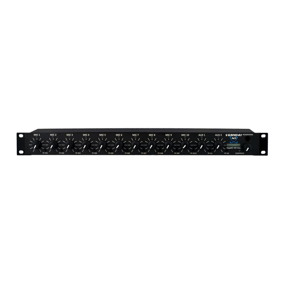
- Page 1 VGM-1041 DSP Gated Mixer / EQ Installation and Use ACI-AppliCAD, Inc. Manual & Firmware version 2.04 Applies to Serial Number Series 15198010035 and above (732) 751-2555 www.aci-applicad.com...
-
Page 3: Table Of Contents
Table of Contents Introduction ------------------------------------------- Features & Benefits Quick Start Guide -------------------------------------- Basic Connections Basic Operation Operator’s Guide --------------------------------------- Front Panel Controls & Indicators Managing Microphones How Sound Gating Works Double Hall Operation Installer’s Guide ---------------------------------------- Mounting, Rear Panel Wiring & Switches Microphone Channel Assignments Line Outputs Adjusting Power Amplifier Gain... -
Page 5: Introduction
Introduction The VGM-1041 DSP Gated Mixer / EQ targets sound reinforcement applications, so your audience enjoys higher quality sound than with generic mixers or consoles. Operators see a compact, refreshingly simple exterior – enabled by the adjustments which you or your installer set up at installation. -
Page 6: Quick Start Guide
Place your VGM-1041 on a table or other flat surface. Audio Source – Using a stereo RCA cable (the sort which often comes with audio components), connect a CD player or a similar “line level”... - Page 7 Quick Start Guide Power – Now for the easy part: Find the supplied 24VDC power adapter. Plug its end into the jack; plug the other end into a power outlet. Your mixer 24 VDC powers ON immediately (some of the DC adapters we supply take a few seconds to start up, this is normal).
- Page 8 Quick Start Guide Hi, Mike! – Connecting a microphone is a bit more challenging – since this mixer is designed for installation, its mic connectors are tool-less terminal blocks. Thus, on-stage cables terminated with XLR (A3M) connectors won’t fit directly. If you have an old cable handy, you could cut it and wire its cut end as shown.
-
Page 9: Basic Operation
• Of course, the level meter indicates the sound level. • Speak loudly enough, and you’ll see the COMPRESS LED illuminate. The VGM-1041’s built-in compression is limiting this mic’s level, preventing excessively loud sound. This feature is selectable for each mic via the mixer’s USB port (covered in the Installer’s Guide section). -
Page 10: Operator's Guide
Operator’s Guide With the VGM-1041 mounted as part of your sound system and set up according to the Installer’s Guide later in this manual, operation is as simple as it could be! Front Panel Controls & Indicators Power – When you power up your sound system, the VGM-1041 goes through a self-check routine which among other things, lights up all front panel LEDs in sequence. - Page 11 Level Bargraph Display – Shows the program level. Its first yellow LED indicates a level of 0 VU – which is equal to +4dBm at the VGM-1041’s balanced output. Each LED above or below this point represents a change of approximately 4 dB in output level.
- Page 12 Operator’s Guide LED – This LED displays the status of the mixer’s compression system. COMPRESS It lights whenever compression is limiting the sound level. For each microphone channel with compression enabled, limiting begins to occur at approximately 0 VU. The LED shows green at 3dB gain reduction,...
-
Page 13: Managing Microphones
Operator’s Guide Managing Microphones – Your goal as sound operator is to provide sufficient, quality sound from all program participants to all in your audience. We’ve prepared this section to help you do this. Your sound system allows participants to speak naturally or even softly as their material requires, confident that the audience hears every word clearly. - Page 14 Proper miking lets everyone be heard with lower gain, resulting in sufficient sound without feedback problems. • The VGM-1041's sound gating automatically increases your available gain before feedback, by muting unused microphones. Unneeded mics receive no useful sound – only feedback and noise. You win about 30% more gain before feedback for each mic gated off.
- Page 15 Operator’s Guide Thanks to the sound gating feature, there’s far less need for you to turn mics up and down during the program. We still recommend, however, turning down mics that are obviously finding only noise: • Mics being moved by stage handlers •...
-
Page 16: How Sound Gating Works
– thus they operate concurrently along with mics. If the VGM-1041 has not been set up properly at installation, you may find that the sound gating performs less than optimally. If for example the gating is not sensitive enough you may notice: •... - Page 17 Operator’s Guide Operation for Double-Hall Installations When linking from the other auditorium is not desired, keep both MIC9 fully down, counterclockwise. MIC10 To listen to the program from the other auditorium, bring up to hear MIC9 the microphones in the other auditorium. Bring up to listen to program MIC10 material (music, etc.) from there.
- Page 18 Operator’s Guide This Page Intentionally Left Blank Don’t you love it when they say that?
-
Page 19: Installer's Guide
Auxiliary Inputs 1 – 2 Down = ON RCA jacks to play line-level sources: 1 – + Output • CD-DVD-MP3 player / computer • 2 – Ground (Shield) Remote conference (receive) 3 – - Output VGM-1041 Rear Panel 1 2 3... - Page 20 Installer’s Guide Channel “Personalities” Recent updates to the VGM-1041’s firmware has added new features, including the ability to link two auditoriums together for overflow audiences. This has affected how microphone channels 9 and 10 work. When assigning channels to your auditorium’s microphones, this chart will help you make the best use of the mixer’s capabilities. The following pages offer suggestions on mic channel assignments: General wired &...
- Page 21 Installer’s Guide Microphones, Cables, and Mounting Arranging Microphone Inputs – The picture below illustrates a typical microphone arrangement. Here we show as your “main” or “chairperson’s” mic. Your mixer’s MIC3 factory settings assume this -- however, you can easily select another input (see page 22). You may of course have microphones at all 10 mic inputs.
- Page 22 Installer’s Guide Wireless mics – If possible, connect each wireless receiver’s mic-level, balanced output to a microphone input of the mixer. This way, the mixer handles each wireless mic as it does other microphones, providing the gating and selectable compression features. Set any level controls on the wireless receivers, and/or the Gain Presets on the mixer’s rear panel, to match their level to that of your wired microphones.
-
Page 23: Line Outputs
Installer’s Guide Line Outputs This mixer features balanced line outputs for your sound reinforcement equipment. There’s also an unbalanced, compressed RCA output for FM transmitters, recording devices, etc. The balanced outputs can provide a level in excess of +20dBm. Following equipment should be capable of a similar maximum level. -
Page 24: Adjusting Power Amplifier Gain
Installer’s Guide Adjusting your Power Amplifier Gain Because the VGM-1041 can be set to compress excessively loud sounds to a consistent level, you need to adjust the rest of your system (power amplifier, etc.) to spot the corresponding auditorium volume as required. This is easy to do if you follow the procedure below. In fact, we recommend following the procedure given below to get your levels “in the ballpark”... -
Page 25: Auto-Eq
Factory Preset Besides the switch settings for phantom power and input gain, your VGM-1041 has many options you can choose via its USB port. These include adjustments for its built-in parametric equalizer, a de-esser, and a pink noise source for system tuning. You can also switch unused inputs to the mixer’s Music path for use with additional music sources. - Page 26 C O M P R E S S To revert to factory presets, hold both the AUX1 and AUX2 Prefade buttons in while switching ON your system’s power (including the VGM-1041). Continue holding until you see their LEDs blink in confirmation. This resets the following functions: •...
- Page 27 The necessary files are included on the flash drive in your package: • Install the FTDI USB Driver • Run PuTTYtel (an open-source terminal program) • Connect your VGM-1041 using a standard USB A-B cable (not included) • Adjust PuTTYtel’s port settings •...
- Page 28 • Run the Puttytel.exe file (it needs no installation). Click through the usual warning: The PuTTYtel application opens, displaying its Configuration screen. Before doing anything there, proceed below to connect your VGM-1041. Connecting your Mixer • Attach a USB A-B cable (not included) to the mixer’s rear panel jack •...
- Page 29 Installer’s Guide • Open Device Manager to find out what COM port you computer has assigned to the mixer. This is easier on some Windows versions than others: o Open your Start Menu, then type Device Manager in the Search box: o Or, from your Start Menu, click Computer, then System Properties: o Then, click Device Manager, which brings up the box shown next page:...
- Page 30 USB Serial Converter and choose Uninstall from its drop-down menu. Confirm this uninstall if asked. • Unplug the VGM-1041 from the USB port. Wait five seconds, then plug it back in. This time, the driver should install correctly.
- Page 31 Installer’s Guide Adjusting PuTTYtel’s Settings • Returning to PuTTYtel, first click the Serial choice. Then set the Serial Line box to the COM port found above, and the Speed box to 115200. Finally, click the Open button. • Press the space bar on your keyboard – you should now see the mixer’s filter-setting screen:...
- Page 32 Installer’s Guide Moving Around the Screen Edit the screen’s settings with your keyboard, as described atop each screen. Your mouse, track pad, and touch screen cannot be used to make these settings: • Navigation Keys: Previous, Next, Left, Right – Or use your keyboard’s arrow keys. •...
- Page 33 OFF, you can do it here. Four separate de-essers reside within the VGM-1041, each handling a pair of mics – MICs 1 and 2, 3 and 4, 5 & 6, 7 & 8. Thus, you can select de-ess ON or OFF for each pair.
- Page 34 Installer’s Guide Optimizing the Sound Gating Follow these instructions if you need to adjust your mixer’s sound gating: First, be sure that your sound system’s audio levels are set up properly. When your mixer is working near its design level, its microcontroller receives detailed information on mic usage, thus can make better gating decisions.
- Page 35 Once you have your source satisfactorily connected to an extra MIC input, the VGM-1041 takes care of the rest. Set the chosen MIC channel’s Base Threshold at zero (0) to route it through the Music path.
- Page 36 Installer’s Guide Equalizer Filter Settings Press F to enter the Filter screen. Each parametric equalizer filter allows setting its: • Center Frequency – from 20 Hz to 20 KHz in 1/6 Octave steps (many more than shown below) • Bandwidth – from 1/6 Octave to 3 Octaves in nine steps...
- Page 37 Installer’s Guide Gain / Attenuation – from -20 dB to +10 dB in 1 dB steps (-9dB to +9dB is shown below): What a Parametric Equalizer Does All the mixer’s EQ filters are parametric. This section introduces parametric filters for those unfamiliar with them.
- Page 38 Installer’s Guide Notice how the response curve mimics the position of the sliders – it’s a graphic EQ! With the graphic EQ you adjust only the gain or attenuation of each filter. Its other parameters – center frequency and bandwidth – are fixed by design. On the other hand, with a parametric EQ you can –...
- Page 39 Installer’s Guide Setting the Music EQ With many “average” sound systems, a modest boost at around 70 Hz, a broad rise centered at perhaps 9 KHz, and some broad attenuation near 300 Hz may improve music reproduction. Experiment with various program material to find good settings. Setting the Individual MIC EQs Making use of each channel’s MIC EQ is entirely optional –...
- Page 40 Installer’s Guide Set Up the Main Voice EQ The VGM-1041’s seven-band parametric Main Voice EQ is where you tune your entire sound system – residual mic responses, speakers, and room acoustics – to provide the best sound. Often, “best sound” means the most gain before feedback. The higher your operators can turn up a mic without problems, the easier it will be for them to give the audience the sound they deserve.
- Page 41 Installer’s Guide Pink Noise Method Pink noise sounds rather like a waterfall. It contains equal energy per octave, resulting in a flat response curve as measured with a Real-Time Analyzer (RTA). Since the pink noise enters your sound system with its characteristic flat amplitude vs. frequency curve, any irregularities in your system and room show up in the actual sound you hear.
- Page 42 While Auto EQ is working, the VGM-1041’s LED bargraph displays the extra gain the mixer is applying to obtain feedback howls. This indication should show about halfway most of the time. Should you find it much above or below halfway, adjust your MIC channel’s gain control slightly,...
- Page 43 Installer’s Guide As described, you can run Auto-EQ without a USB connection to your computer – yet the USB port provides additional information you may find helpful. With your computer connected and communication established (see pages 23-28), you can start Auto-EQ by pressing the hotkey sequence EQ.
- Page 44 Installer’s Guide Graphing your Filters’ Frequency Response The VGM-1041 can show the frequency response curve resulting from present EQ settings. To access this feature, press G. Return to the previous screen by pressing the space bar. Thus you can easily switch between setting filters and viewing the results.
- Page 45 Installer’s Guide When you press G while the Filter screen is pointing to a Music filter, you get the entire Music Filter response: Finally, if your Filter screen is pointing to any Individual Channel filter: …your plot shows the response of the two individual channel filters added to: •...
-
Page 46: Double-Hall Installation
Installer’s Guide Double Hall Installations You can link the mixers in two auditoriums together to provide sound to an overflow audience. The linkage can be one-way or two-way, and for voice (mics), music (aux), or both. This feature makes use of MIC channels 9 & 10, making these unavailable for mics in a double-hall installation. - Page 47 Installer’s Guide The recommended Mic Screen settings for use with a double-hall installation are shown below: We recommend setting Mic 9’s Stage Monitor off on both mixers, to help prevent acoustic feedback between both auditoriums.
-
Page 48: In Case Of Difficulty
1041 has no power switch!). To minimize power problems, we recommend installing a “master switch” for the entire sound system. A functioning VGM-1041 completes its self-test (the “light show”) when first powered up, after which at least one front panel LED remains lit at all times. If the “light show”... - Page 49 – system and this manual are close at hand. You may call ACI-AppliCAD at (732) 751-2555 during normal business hours (Eastern Time) to get help with installing, using, or troubleshooting your mixer. If it appears that your mixer is defective, we’ll issue a RMA (Return Material Authorization) number for factory service.
-
Page 50: Specifications & Flow Diagram
Specifications Inputs & Outputs: • 10 Mic inputs. Balanced, Low-Z, solderless, tool-less connectors Individually selectable compression and 24V phantom power Each configurable as an extra AUX (Music) input • 2 AUX inputs. Unbalanced RCA • 4 Balanced outputs: Main, Voice, Music, and Stage Monitor •... - Page 51 Flow Diagram...
-
Page 52: Index
Index Microphones 4, 15 – 18 uto-EQ – Condenser 4, 18 uxiliary Inputs 2, 15 35 – 37 Management alanced Outputs 15, 19 Wireless Bench test 2 – 5 Wiring 4, 15 Mounting ompression 5, 10 – 11, 29 Music EQ COMPRESS LED 8, 10 –...
Need help?
Do you have a question about the VGM-1041 and is the answer not in the manual?
Questions and answers