Advertisement
Quick Links
Specifications
Transformer
300W
120V Primary Breaker
4A
240V Primary Breaker
2A
Secondary Breaker
10A
Motor Voltage
26-32V
Troubleshooting
My motor is not running. Confirm presence of 26-32V DC at the relay board terminals labeled "-24V+"
(NOT the terminals labeled ("+24V"). If this voltage is not present, it is likely that the rectifier is damaged.
My breaker is tripping. (1) This is usually a sign of a damaged rectifier. Apply power with the DC rectifier
terminals disconnected. If the breaker still trips, the rectifier needs replacement. (2) If the breaker does not
trip with the DC rectifier terminals disconnected, disconnect the "24V+" wires from the relay boards one
board at a timeto determine if the breaker trips. The board causing the tripping is suspect and should be
substituted or replaced.
Temperature Sensor Troubleshooting
LED Flashing F1 and Temperature: LED Flashing F1 and Temperature - F1 is the fault code for a
disconnected temperature sensor. Check to ensure the red, and white sensor wires are in the correct
location and securely connected. The wires may appear to be connected but not making good contact.
Disconnecting and reconnecting the sensor wires clears the fault in most occurrences.
LED Flashing F2: The F2 fault code indicates a damaged or short-circuit of the temperature sensor.
Temperature sensor failures are rare and usually caused by improper splicing or physical damage. If an F2
fault condition is present, please contact Technical Support - 877.546.2257.
Temperature Reading Fluctuates: The LED temperature reading continually indicates large swings in
temperature. Temperature fluctuations occur when the sensor wire runs parallel to power lines,
(120/220V AC). Do not run temperature sensor wire inside of conduit alongside power lines. Make all
sensor wire crossings at 90° to power lines.
Heater Troubleshooting
Heater Does Not Come on at Setpoint: Check the configuration setting C19 to verify it is set to a value of
at least 1 to enable the heater. The heater thermostat wires must be connected to contact #3 when only 1
heater is present. Verify parameter settings P5 – P7 is set to the desired setpoints and hysteresis. Check
heater manufacturer documentation to confirm thermostat wires correct installed.
Fan(s or Louver(s)
Check configuration setting C19 is set to a maximum value of 1 to enable the fan/louver. The fan/louver
must be connected to the vent control unit via an AC contactor box. Do not connect fans/louvers directly
to the relay board. Confirm the AC contactor box connection is at contact #4 and the additional wiring
required corresponds to the diagram on page 11. Check parameter setting P6 is set to the desired
setpoint.
All electrical connections must be made by a
qualified, licensed electrician. All connections must be
made in accordance with all state and local codes.
The inside of the box housing the transformer has
high voltage which can be dangerous.
Safety Information:
SHOCK HAZARD Electric shock can kill.
Touching live electrical parts can cause fatal
shocks or severe burns.
What's Included:
Mounting
Temperature
Brackets (x4)
Sensor
Plug-In Relays
41-VCU2-24
(x4)
Mounting screws
Images not to scale.
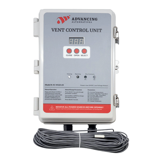
41-VCU2-24
Vent Control Unit
Quick Start Guide
Scan the QR Code to visit our
Knowledge Center, which features the
full instruction manual and other
resources.
Warranty Registration:
advancingalternatives.com/register
Visit Advancing Alternatives' YouTube
Channel to Access Video Tutorials
IMPORTANT
For detailed instructions and technical support, visit
advancingalternatives.com/knowledge-center
WARNING All electrical connections
must be made by a qualified, licensed
electrician. All connections must be
made in accordance with all state and
local codes.
Tools & Materials Required:
Screwdriver (#1)
Motor wire
Wire crimper
14 AWG for less
Drill with 7/8" bit
than 100'
connections
(if using provided
12 AWG for
cable glands)
connections over
100'
Signal Wire
*Breakers Required for Motors
LVM-60: 3A breaker
LVM-180: 7.5A breaker
(x4)
LVM-100: 5A breaker
LVM-200: 10A breaker
18-22 AWG
Advertisement

Summary of Contents for Advancing Alternatives 41-VCU2-24
- Page 1 If the breaker still trips, the rectifier needs replacement. (2) If the breaker does not trip with the DC rectifier terminals disconnected, disconnect the “24V+” wires from the relay boards one Visit Advancing Alternatives’ YouTube board at a timeto determine if the breaker trips. The board causing the tripping is suspect and should be Channel to Access Video Tutorials substituted or replaced.
- Page 2 Configuration CAUTION: Equipment Damage PLEASE NOTE: Illustrations for example purposes Do not expose the 41-VCU2-24 to weather. only. Actual wiring and layout may vary. Read the Press and release “SELECT” to cycle through the configuration menu. To Locate in a dry, protected area to prevent 41-VCU2-24 instruction manual for full details.
Need help?
Do you have a question about the 41-VCU2-24 and is the answer not in the manual?
Questions and answers