
Summary of Contents for LiteOn Pii EVQC0 M R Series
- Page 1 Mobile EV Quick Charger Models: EVQC0xx-MxRx and EVQC0xx-MxBx Installation and Operation Manual MNL217...
- Page 2 Please contact Power Innovations if you need additional guides or manuals and have not received them. Product names mentioned herein may be trademarks (™) and/or registered trademarks (®) of their respective companies, which may include Power Innovations International, Inc. (part of LiteOn Group), LiteOn Technology Corporation, or a third party. Copyright © 2023-2024 Power Innovations International, Inc.;...
-
Page 3: Table Of Contents
1— Product Overview ................................1 Introduction ................................1 Highlighted Features of Mobile EV Quick Chargers ....................1 Charger Features Identified ............................2 Symbols Used in this Manual ........................... 3 Acronyms Used in this Manual ..........................3 2— Safety and Specifications .............................. 4 IMPORTANT SAFETY INSTRUCTIONS –... - Page 4 This page left blank intentionally. iv | MNL217 03/19/2024...
-
Page 5: 1-Product Overview
1—Product Overview This section provides product overview to Power Innovations International Mobile EV Quick Charger models--those with RFID only (EVQC0xx-MxRx series) and those with both RFID and Modem (EVQC0xx-MxBx series). Introduction This EV quick charger is an electric vehicle (EV) power supply that is on swivel casters with locks so it can be easily moved to different locations within a facility. -
Page 6: Charger Features Identified
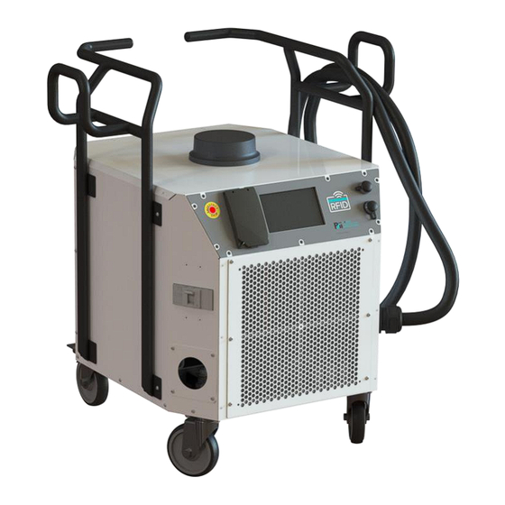
Charger Features Identified Handlebars Cellular Antenna (models with modem only) AC Input Cord Hanger User Interface Hanger for LCD Screen DC Output/ Charging Cable E-Stop RJ45 Bulkhead Connector Power Up & Down Buttons under Cover RFID Reader AC Main Switch CCS1 DC Output/ Front Panel Charging Cable... -
Page 7: Symbols Used In This Manual
Symbols Used in this Manual Icons or symbols are occasionally used throughout this manual to help identify safety warnings and other pertinent content contained here. These icons are described in the table below. Icon Type of Warning Description WARNING! RISK OF ELECTRIC SHOCK! ELECTRICAL WARNINGS ADDITIONAL TEXT THAT FOLLOWS THIS SYMBOL PROVIDES MORE INFORMATION ABOUT THE... -
Page 8: 2-Safety And Specifications
2—Safety and Specifications The following safety instructions apply throughout the EV Charger installation process. Be familiar with them before moving on to the next section to complete the installation. IMPORTANT SAFETY INSTRUCTIONS – SAVE THESE INSTRUCTIONS ELECTRICAL WARNINGS – WARNING! RISK OF ELECTRIC SHOCK! WARNING! RISK OF ELECTRIC SHOCK! ONLY QUALIFIED ELECTRICAL PERSONNEL FAMILIAR WITH THE CONSTUCTION AND OPERATION OF THIS TYPE OF EQUIPMENT AND THE HAZARDS INVOLVED SHOULD... -
Page 9: Specifications - Mobile Ev Quick Charger Models Evqc0Xx-Mxxx
Specifications – Mobile EV Quick Charger Models EVQC0xx-Mxxx Electrical Specifications AC Input AC Input Power Options 240V single-phase (Field configuration patent pending) 208/240V 3-phase Delta (3-wire + PE) 480V 3-phase Wye (3-wire + Neutral + PE) AC Input Voltage Operating Range and 240V single phase: 190V to 305V, 225A max, 60 Hz Current 208V/240V 3 phase Delta:190V to 264V, 172A max, 60 Hz... -
Page 10: 3-Installing Ev Charger
3—Installing EV Charger ELECTRICAL WARNINGS – WARNING! RISK OF ELECTRIC SHOCK! WARNING! RISK OF ELECTRIC SHOCK! SHUT OFF POWER SUPPLY BEFORE BEGINNING INSTALLATION ACTIVITIES AND BEFORE REMOVING EV QUICK CHARGER’S AC SERVICE PANEL FOR ANY INSTALLATION OR MAINTENANCE WORK. FAILURE TO OBSERVE THIS PRECAUTION COULD RESULT IN SEVERE INJURY OR DEATH. -
Page 11: What's Provided With Charger
What’s Provided with Charger EVQC0xx-MxRx or EVQC0xx-MxBx Description 1 Mobile EV Quick Charger model (with or without modem and cellular antenna), for up to DC 60kW output, fully assembled exterior Up to 6 Shelf Controllers (SCs) Up to 18 Power Supply Units (PSUs) 3 Configuration Bus Bars, each uniquely configured (ship anchored in storage location inside charger) 4 cable plates (1.5”, 2”, 2.5”, 3”... -
Page 12: Prepare Installation Site
Prepare Installation Site Become familiar with basic dimensions of the Mobile EV Quick Charger and Installation Site warning and best practice(s). Basic dimensions of Mobile EV Quick Charger, models EVQC0xx-MxRx and EVQC060-MxBx, with hangers and swivel casters are shown in Figure 3. Figure 3—Depth, Width, and Height of Mobile Charger (includes Handles and Wheels) Select storage and operation locations that are not hazardous. -
Page 13: Install Power Supply Units And Shelf Controllers
Install Power Supply Units and Shelf Controllers ELECTRICAL WARNINGS – WARNING! RISK OF ELECTRIC SHOCK! WARNING! RISK OF ELECTRIC SHOCK! ENSURE POWER SUPPLY IS SHUT OFF BEFORE STARTING OR CONTINUING INSTALLATION ACTIVITIES AND BEFORE OPENING EV QUICK CHARGER’S PANELS. FAILURE TO OBSERVE THIS PRECAUTION COULD RESULT IN SEVERE INJURY OR DEATH. - Page 14 Using a T25 Torx t-handle screwdriver, remove 16 buttonhead screws around perimeter of rear cover securing charger’s rear cover (Figure 6) to charger, then lift cover slightly and pull bottom end out first to then lower and remove cover from charger. Figure 6—Removal of Rear Cover with Screen still attached Insert up to 6 Shelf Controllers (SCs), 1 on each shelf (Figure 7) and secure with built-in screw (Figure 8).
- Page 15 Insert up to 18 power supply units (PSUs), 3 on each shelf (Figure 9) and ensure each PSU release lever clicks into the locked position Load the shelves from the bottom up so that any open slots for PSUs end up on the top shelves.
-
Page 16: Configure Cellular Modem (If Available On Unit) And Register On Network
Configure Cellular Modem (if available on Unit) and Register on Network If a cellular modem is not installed on your mobile charger, skip to Section 3.6. WARNING! RISK OF ELECTRIC SHOCK! DO NOT CONNECT POWER SUPPLY TO EV QUICK CHARGER UNTIL SIM CARDS ARE INSERTED INTO CELLULAR MODEM AND TOP PANEL COVER AND SCREWS ARE REINSTATED. -
Page 17: Configure And Wire Ac Input Power
Register this EV charger as one of the supported devices on the owner’s backend network. Later when you configure and wire the AC power input and you apply power to the charger, the modem will find the cellular network and attempt to automatically connect. If you’re ready to configure and wire AC input power, leave the rear cover off and skip to next section. - Page 18 If charger’s rear cover is on, use a T25 Torx t-handle screwdriver to remove the 16 buttonhead screws around rear cover’s perimeter, then lift cover slightly and pull bottom end out first to then lower and remove cover from charger; then set cover and screws aside (see Figure 14). Figure 14—...
- Page 19 Do not store or operate this mobile quick charger in a hazardous location. WARNING! RISK OF ELECTRIC SHOCK! DO NOT STORE OR OPERATE CHARGER IN A HAZARDOUS LOCATION! Open front panel of charger using a T25 Torx t-handle screwdriver to remove 6 buttonhead screws around the perimeter of the front panel, then set panel and screws aside (see Figure 16).
- Page 20 Install the Configuration Bus Bar required for this charger’s AC input power as follows: a. Place selected Configuration Bus Bar on the Bus Bar with its “FRONT” stamp facing out (such as the “FRONT – 480 WYE” example shown in Figure 18). b.
- Page 21 Notice the three AC input power wiring configurations shown in Figure 21, then select the wiring configuration and ring terminals needed for this charger. • Ring terminal (ring lug) for Neutral or a Line wire must fit 3/8-inch diameter junction block stud. •...
-
Page 22: 4-Setting Up Power Level And Operating Ev Quick Charger
4—Setting Up Power Level and Operating EV Quick Charger Set Power Level for Desired Operating Location 4.1.1 Do not store or operate this mobile quick charger in a hazardous location. WARNING! RISK OF ELECTRIC SHOCK! DO NOT STORE OR OPERATE CHARGER IN A HAZARDOUS LOCATION! 4.1.2 Calculate Maximum Charger Power Level allowed for current location using configuration information and this table (also found on a label provided). - Page 23 4.1.4 Set Maximum Charging Power setting at or below your calculation in step 1 as follows: Figure 24—Lift button cover and press top and bottom button simultaneously to enter Configuration Mode 4.1.5 Lift button cover on front of charger, then press top and bottom buttons at same time (Figure 24) to enter Configuration Mode.
-
Page 24: Operate Ev Quick Charger
Operate EV Quick Charger 4.2.1 Click to release EV cable plug from docking station and plug into EV. 4.2.2 Use one of the payment methods your charger supports to initiate a charging session. For example, if using an RFID card provided for this charger, tap the card on the charger’s RFID Reader. 4.2.3 Watch display for payment authorization: If payment method was accepted, the message “Authorized”... - Page 25 4.2.4 Follow on-screen displays to ensure charger connects to vehicle and the charging cycle begins. Once charging cycle successfully starts, the charging progress displays. 4.2.5 The charger will automatically complete the charging cycle if left undisturbed. If you wish to stop charging cycle early, press any button.
-
Page 26: 5-Maintaining Ev Charger
5—Maintaining EV Charger ELECTRICAL WARNING: SHUT OFF POWER SUPPLY BEFORE BEGINNING INSTALLATION ACTIVITIES AND BEFORE REMOVING EV QUICK CHARGER’S AC SERVICE PANEL FOR ANY MAINTENANCE WORK. FAILURE TO OBSERVE THIS PRECAUTION COULD RESULT IN SEVERE INJURY OR DEATH. CAUTION! Maintenance tasks should only be completed as directed in this section. When in doubt, contact Power Innovations on how to proceed. -
Page 27: Replace Air Filter
Replace Air Filter The chargers filter can be replaced. Please contact Power Innovations for replacement part or order from McMaster Carr: Part Number 2150K17. Restart after Emergency Stop This Emergency Stop button is an emergency ON/OFF operator button for the quick charger’s charging sessions. Any time the Emergency Stop button has been pressed and is recessed, it is in the OFF position. -
Page 28: 6-Regulatory
6—Regulatory This product and its documentation comply with the following UL Standards: • UL 2202 Standard for Safety: Electric Vehicle (EV) Charging System Equipment • UL 2231-1 Standard for Safety: Personnel Protection Systems for Electric Vehicle (EV) Supply Circuits; Part 1: General Requirements 7—Warranty Power Innovations International warrants that products purchased hereunder are free and clear of all liens and... -
Page 29: 8-Contact Information
8—Contact Information If there are any questions or comments about this product, please feel free to contact us. Power Innovations International, Inc. Web: www.powerinnovations.com/support Phone: 801-785-4123 Mailing Address: 1305 South 630 East, American Fork, UT 84003 Copyright © 2023-2024 Power Innovations International, Inc. American Fork, UT, USA All rights reserved.
Need help?
Do you have a question about the Pii EVQC0 M R Series and is the answer not in the manual?
Questions and answers