Table of Contents
Advertisement
Quick Links
PROJECT NAME
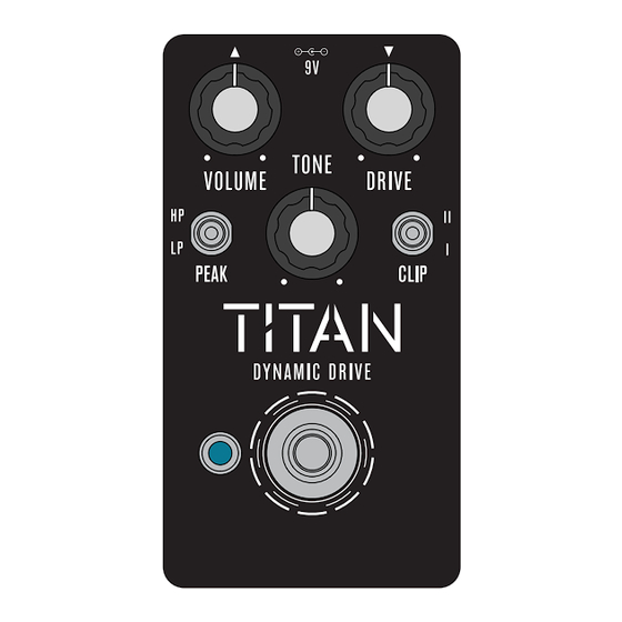
TITAN
BASED ON
Fulltone
OCD
®
EFFECT TYPE
Overdrive / distortion
PROJECT SUMMARY
A legendary hard-clipping overdrive pedal that makes almost any rig sound better.
This documentation is for the kit version of the project. If you purchased the PCB by itself, please use the
PCB-only version
of the documentation instead. The circuit is the same, but the instructions are completely
different due to the specialized parts and assembly methods used in the kit.
®
Fulltone
and OCD
trademarks is for comparative purposes only. Aion FX has no affiliation with Fulltone Musical Products and
this project is not endorsed by them.
TITAN DYNAMIC DRIVE
®
®
are registered trademarks of Fulltone Musical Products LLC. Any use of these
BUILD DIFFICULTY
Easy
DOCUMENT VERSION
1.0.1 (2024-02-06)
IMPORTANT NOTE
TRADEMARK USAGE
1
Advertisement
Table of Contents

Related Manuals for aion Fulltone OCD TITAN


Summary of Contents for aion Fulltone OCD TITAN
- Page 1 OCD are registered trademarks of Fulltone Musical Products LLC. Any use of these trademarks is for comparative purposes only. Aion FX has no affiliation with Fulltone Musical Products and this project is not endorsed by them. TITAN DYNAMIC DRIVE...
-
Page 2: Table Of Contents
TABLE OF CONTENTS 1 Project Overview 2 Table of Contents 3 Introduction 4 Packing List 5 Packing List (Cont.) 6 Tools Needed 7 Component Identification 8 Hardware Identification 9 PCB Assembly Overview 10 Resistors 11 Diodes & LEDs 12 Socket & IC 13 DIP Switches 14 Transistors 15 Capacitors (Non-Polarized) -
Page 3: Introduction
INTRODUCTION If this is your first pedal, welcome to the hobby and thank you for choosing Aion FX. You’ve just joined a community of over 40,000 people around the world with a passion for building homemade noise machines using obsolete electronics technologies, and we’re glad to have you! If you’ve done this before, it’s great to see you again and we’re confident you’ll find this build experience... - Page 4 PACKING LIST This is a list of all the parts that are included with the kit, grouped by value. For a list of all the parts based on their PCB part numbers, please see page 28. If you find that any parts are missing or damaged, please fill out the Missing Parts form.
- Page 5 PACKING LIST (CONT.) Potentiometers Switches NAME NAME 10kB Toggle switch, SPDT on-on 100kB Mounting nut, toggle switch, 0.36" Lock washer, toggle switch, 0.4" Dust cover Dress nut, toggle switch, 0.375" Knob Stomp switch, 3PDT Mounting nut, potentiometer, 0.44" Mounting nut, stomp switch, 0.6" Lock washer, potentiometer, 0.5"...
-
Page 6: Tools Needed
TOOLS NEEDED SOLDERING IRON SOLDER DIGITAL MULTIMETER (DMM) Temperature-adjustable is Preferably 63/37 or 60/40 leaded Most cheap ones in the $10-30 range recommended. The optimum solder. Lead-free is more difficult to are fine for what we’re doing. Make soldering temperature is 700-725º use, so if that’s the only type you can sure it has audible continuity testing F (371-385º... -
Page 7: Component Identification
COMPONENT IDENTIFICATION If you’ve never built a pedal before, you’ll need to know what all the components are. These are shown actual size. (Not all of these types of components may be part of this kit.) RESISTOR TRIMMER POTENTIOMETER SILICON DIODE GERMANIUM DIODE RECTIFIER DIODE SCHOTTKY DIODE... -
Page 8: Hardware Identification
HARDWARE IDENTIFICATION The hardware comes unassembled, so you’ll need to sort & identify each of the pieces. The diagrams below are actual size, so you can set them against the printed page to identify them if needed. I/O JACK MOUNTING NUT OUTER WASHER LOCK WASHER DIAMETER: 0.54”... -
Page 9: Pcb Assembly Overview
PCB ASSEMBLY OVERVIEW Now it’s time to start building! The first thing you need to do is separate the PCBs into 3 separate boards and break off the tabs from each using needle-nose or flat-head pliers. You should be left with the PCBs shown to the right. The general principle for PCB population is that you want to work in layers from shortest components (i.e. -
Page 10: Resistors
RESISTORS PART VALUE PART VALUE PART VALUE 150k 470k 100R LEDR Using the parts list above, populate the resistors by pushing them through the holes and bending the leads outward at an angle to hold them in place. Resistors are not polarized, so they will work in any direction. -
Page 11: Diodes & Leds
DIODES & LEDS PART VALUE PART VALUE 1N5817 3mm red LED Germanium 3mm red LED Germanium Next, you’ll populate the diodes. Diodes are polarized, so make sure to identify the polarity band (which indicates the “cathode”, or negative side) and match the band to the footprint on the PCB. Precautions with germanium diodes Germanium diodes are fragile and require more care than the other components. -
Page 12: Socket & Ic
SOCKET & IC PART VALUE TL082 Next up is the IC socket. You can’t bend the leads of the socket like you can with the other components, so it won’t stay in on its own until it is soldered. Again, it’s much easier to do this with gravity holding it in place for you, so you’ll want install the socket before you do any of the taller components. -
Page 13: Dip Switches
DIP SWITCH & TRIMMER 3-position DIP switch (2) Now we’ll do the DIP switches. These are both very slightly taller than the IC socket, so they should be done after the socket is soldered, but the process is the same. The legs of the DIP switches aren’t long enough to be bent, so just turn the PCB upside down and let it hold the DIP switch in place while you solder. - Page 14 TRANSISTORS AND REGULATOR PART VALUE 2N7000 2N7000 Now we’ll do the transistors as well as the regulator, which is not a transistor but looks like one. For each, if the legs are not already bent into 0.1” spacing, use your needle-nose pliers to bend the outer two legs as shown.
-
Page 15: Capacitors (Non-Polarized)
CAPACITORS (NON-POLARIZED) PART VALUE PART VALUE 22n (0.022) 47n (0.047) 220pF (221) 47n (0.047) 68n (0.068) 47n (0.047) 1n (0.001) 10n (0.01) 220pF (221) 33n (0.033) 100n (0.1) 100n (0.1) After the sockets come the box film and MLCC capacitors. These are all several different heights, but there aren’t as many, so just do them all at once. -
Page 16: Wire Headers & Trimmer
WIRE HEADERS Install the two 3-pin headers (wire connectors) as shown above. These have a polarity pin, so as long as they are pressed all the way down, there’s only one possible way to install them. They do fit pretty tightly in the holes, though, so press firmly. -
Page 17: Capacitors (Polarized)
CAPACITORS (POLARIZED) PART VALUE 47uF electro 100uF electro Populate the electrolytic capacitors. These are the tallest components so we save them for last. They are polarized (i.e. they will only work in one direction), so note the vertical mark that indicates the negative side. -
Page 18: Footswitch Pcb
FOOTSWITCH PCB PARTS 3-strand wire assembly (2) 4-strand wire assembly Next, it’s time to finish up the footswitch board. You should have done most of the on-board components on this board in a previous step, but if not, go back and do those. There will be one longer assembly with 4 wires and two shorter ones with 3 wires. -
Page 19: Input/Output Pcb
INPUT/OUTPUT PCB PARTS Input & output jacks DC jack Wire header 9V battery snap Almost done! Get the two input/output jacks, the DC jack and the wire header and snap them in place. The PCB is designed for them to fit securely, so you can do them all at once before flipping and soldering. After you’ve soldered everything, make sure to snip the leads on the I/O jacks as close as possible to the PCB. -
Page 20: Enclosure Layout: Panel Mounts
ENCLOSURE LAYOUT: PANEL MOUNTS Attach the hardware to the enclosure as shown. (The I/O board is done in a later step.) FOOTSWITCH 100kB 10kB SPDT SPDT on-on on-on MOUNTING NUT LOCK WASHER BEZEL & LED MOUNTING NUT DRESS NUT FOOTSWITCH The dress nut fits over the top of the mounting nut and is for aesthetic purposes only. -
Page 21: Enclosure Layout: Panel Mounts (Cont.)
ENCLOSURE LAYOUT: PANEL MOUNTS (CONT.) Attach the toggle switches to the enclosure as shown in the diagram. TOGGLE SWITCH 100kB 10kB SPDT SPDT on-on on-on MOUNTING NUT LOCK WASHER BEZEL MOUNTING NUT & LED The dress nut acts as a mounting nut, unlike the footswitch dress nut. Use flat- nose pliers on the flat sides of the nut to tighten securely. -
Page 22: Enclosure Layout: Main & Footswitch Pcbs
However, Aion FX projects are designed to be extremely easy to remove from the enclosure for troubleshooting, with no desoldering required—so with these kits, it’s actually much easier to “box it before you rock it”. -
Page 23: Enclosure Layout: Input/Output Pcb
ENCLOSURE LAYOUT: INPUT/OUTPUT PCB Affix the input/output PCB to the north-facing panel of the enclosure as shown. Note the use of two mounting nuts on each of the jacks, one inside and one outside. The inner nut acts as a spacer to set the DC jack flush with the outside of the enclosure. The inner nuts should be threaded as far down as they can go. -
Page 24: Final Testing & Assembly
FINAL TESTING & ASSEMBLY After everything is in place, just plug the 3 wire assemblies into their respective headers and make sure they’re secure. That’s it! Here is a cross-section of the inside of the completed pedal. At this point, you have completed the full circuit as far as the electrons are concerned. Plug in a 9-volt supply and test it out with a guitar and an amplifier. -
Page 25: Usage
USAGE The Titan has the typical controls of a 3-knob overdrive: • Drive controls the amount of gain pushed into the hard-clipping diodes. • Tone controls the treble response via a passive filter. • Volume controls the overall output. There are also two toggle switches: •... -
Page 26: Dip Switch Quick Reference
DIP SWITCH QUICK REFERENCE ® The DIP switches capture the main differences in voicing between each version of the original OCD However, not all of the circuit changes can be put on switches, particularly the different potentiometer values and tapers that were used throughout the manufacturing run, so we’ve also included notes on the remaining differences. -
Page 27: Schematic
SCHEMATIC 100R 1N5817 100uF 47uF 100n HP/LP IC1A IC1B TL082P TL082P D4 D5 220pF 100n 220pF 2N7000 150k DRIVE TITAN DYNAMIC DRIVE... -
Page 28: Full Parts List
FULL PARTS LIST In this document, the parts list is spread out across several pages by step. For more experienced builders, though, it may be easier to have everything in one place. Resistors PART VALUE PART VALUE PART VALUE 150k 470k 100R LEDR... -
Page 29: Troubleshooting Information
TROUBLESHOOTING INFORMATION What happens if you finish building the kit and find that it doesn’t work right? Here are a few common problems people have with this pedal and how to solve them. The LED doesn’t light up. First, does the pedal sound right? If you aren’t getting any sound, you probably have a power issue with the whole circuit that is not specific to the LED, so you’ll want to look elsewhere for the problem. - Page 30 “goop” the PCB or otherwise obscure the source. In other words: you don’t have to go out of your way to advertise the fact that you use Aion FX kits, but please don’t go out of your way to hide it.
- Page 31 These kits are intended to be built by the customer. Aion FX is not responsible for language that may be used by the customer in the marketing or resale of the finished product.
Need help?
Do you have a question about the Fulltone OCD TITAN and is the answer not in the manual?
Questions and answers