Table of Contents
Advertisement
Quick Links
Advertisement
Table of Contents

Summary of Contents for Mobile LLS22NU-DM
- Page 2 FOREWARD Before operating the electric stacker, read this ORIGINAL INSTRUCTION HANDBOOK carefully and understand the usage of the truck completely. Improper operation of the truck may create a danger situation. This handbook describes the usage of different electric stackers. When operating and servicing the truck, make sure, that it applies to your type.
-
Page 3: Table Of Contents
TABLE OF CONTENTS CORRECT APPLICATION ........................3 DESCRIPTION OF THE STACKER ....................4 Overview of the main components....................4 Main technical data ........................5 Description of the safety devices and warning labels ..............9 Identification plate ........................10 WARNINGS, RESIDUAL RISK AND SAFETY INSTRUCTIONS ............10 COMMISSIONING, TRANSPORTING, DECOMMISIONING............11 Commissioning..........................11 Lifting/transportation........................11 Decommissioning.........................12... -
Page 4: Correct Application
1. CORRECT APPLICATION t is only allowed to use this electric stacker according to this instruction handbook. The trucks described in this handbook are self propelled pedestrian controlled electric power stacker, with electrically operated lifting function. The trucks are designed for stacking operations in dedicated racking by lifting and lowering the palletized load up to the desired lifting height. -
Page 5: Description Of The Stacker
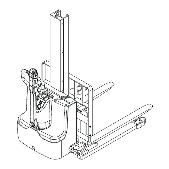
2. DESCRIPTION OF THE STACKER Overview of the main components Drive motor cover 10 Accelerator (butterfly- switch) Balance wheel 11 Multifunction tiller Drive wheel 12 Electricity meter Hydraulic cylinder 13 Chassis with mast Charging cable 14 Leg Main cover 15 Load wheel Emergency button 16 Charging indicating LED Key switch... -
Page 6: Main Technical Data
Main technical data Fig. 2: Technical data (LLS22NU-DM) Table 1: Main technical data for standard version (LLS22NU-DM) Type sheet for industrial truck acc. to VDI 2198 Manufacturer`s type LLS22-114NU-DM LLS22-126NU-DM LLS22-138NU-DM designation Battery Drive Pedestrian Operator type Q(t) 1000 Load capacity / rated load... - Page 7 (mm) 1070-1370 Tread, rear Lowered mast height (mm) 1945 2095 2245 (mm) Free Lift height Lift (mm) 2840 3140 3440 Extended mast height (mm) 3420 3720 4020 Height of tiller in drive position 825/1250 min./ max. 4.15 Height, lowered 4.19 (mm) 1810 Overall length...
- Page 8 Fig. 3: Technical data (LLS22NU) Table 2: Main technical data for standard version (LLS22NU) Type sheet for industrial truck acc. to VDI 2198 LLS22-63NU LLS22-79NU Manufacturer`s type designation Drive Battery Operator type Pedestrian Load capacity / rated load Q(t) 1000 C(mm) Load centre distance X(mm)
- Page 9 4.20 (mm) Length to face of forks 4.21 (mm) Overall width 4.22 s/ e/ l(mm) 35/100/1150 Fork dimensions 4.25 Width across forks (mm) 252-800 4.32 Ground clearance, centre of wheelbase m2(mm) 4.33 Aisle width for pallets 1000X1200 crossways Ast (mm) 2262 4.34 Ast (mm)
-
Page 10: Description Of The Safety Devices And Warning Labels
c. Description of the safety devices and warning labels Fig. 4: Warning labels and safety devices Fig. 2: Technical data Crane hook label Warning decal: Do not step under or on the forks Residual lift capacity sticker Sticker to read and follow these instructions ‘No passengers’... -
Page 11: Identification Plate
Identification plate Designation, type Name and address of manufacturer) Serial number Battery weight minimum/ maximum Rated capacity in kg Nominal power in kW Supply voltage in V Load center distance Own mass (self weight) in kg without 10 Manufacturing data battery 11 Option Fig. -
Page 12: Commissioning, Transporting, Decommisioning
Watch difference in floor levels when driving. Load could fall down or the truck could get uncontrollable. Keep watching the condition of load. Stop operating the truck if load becomes unstable. Brake the truck and activate the emergency button (7) by pushing when sliding load on or off the truck. - Page 13 Park the truck securely and lash the truck according to the points identified in Fig. 6 Lift the truck to its destination and place the truck securely before removing the lifting gear. Fig. 6: Lifting with a crane Transportation DURING TRANSPORTATION ON A LORRY OR TRUCK ALWAYS FASTEN THE TRUCK SECURELY Lower the forks and park the truck securely.
-
Page 14: Decommissioning
Decommissioning For storage, remove the load, lower the truck to the lowest position, grease all in this handbook mentioned greasing points (regular inspection), eventual protect the truck against corrosion and dust. Remove the batteries and jack the truck safety, so that there will be no flattening after storage. For final decommissioning hand the truck to a designated recycling company. -
Page 15: Parking
Press the horn button 21(Fig 8) to activate the audible warning signal. Fig. 9: Key switch Fig.8: Tiller operating controls Parking DO NOT PARK THE TRUCK ON INCLINED SURFACES The truck is equipped with an electromagnetic failsafe stopping and parking brake. Always lower the forks fully and drive the truck to a safe area. -
Page 16: Lifting
DO NOT OVERLOAD THE TRUCK! THE MAXIMUM CAPACITY IS 1000 kg LIFT ONLY CAPACITIES ACCORDING TO THE RESIDUAL LIFT DIAGRAM. Travel with the lowered forks fully underneath the pallet and press the lifting button (Fig. 8, 22) until you reached the desired lifting height. Lowering If the forks are in the racking, firstly travel out of the racking carefully with or without the pallet. -
Page 17: Steering
If you move the accelerator button back to the neutral position, the controller decelerates the truck until thetruck stops. If the truck stopped, the parking brake will be engaged. Drive carefully the truck to the destination. Watch the route conditions and adjust the travelling speed with the accelerator- button. -
Page 18: Battery Changing And Replacement
7. BATTERY CHANGING AND REPLACEMENT • Only qualified personnel are allowed to service or charge the batteries. The instructions of this handbook and from the battery- manufacturer must be observed. • These batteries are maintenance free; re- filling is prohibited. •... -
Page 19: Battery Indicator
Battery indicator PLUG The discharge status is indicated by ten red LED segments. Battery discharged Battery charged discharged Fig.15: Battery charging Fig.14: Battery discharge indicator Only when the battery is properly charged, the most right LED lit. As the battery’s state-of-charge decreases, successive LEDs light up, only one on at a time. -
Page 20: Regular Maintenance
8. REGULAR MAINTENANCE • Only qualified and trained personnel are allowed to do maintenance on this truck. • Before maintaining, remove the load and lower the forks to the lowest position. • If you need to lift the truck, follow chapter 4 b by using designated lashing or jacking equipment. - Page 21 • 20 Test the display • 21 Check if correct fuses are used, if necessary replace. • 22 Test the audio warning signal • 23 Check the contactors • 24 Check the frame leakage (insulation test) • 25 Check function and wear of the accelerator •...
-
Page 22: Lubricating Points
Lubricating points Lubricate the marked points according to the maintenance checklist. The required grease specification is: DIN 51825, standard grease. Bearings in wheels Main frame post Chain Hydraulic system Steering bearing Gear box Fig. 17: Lubricating points Check and refill hydraulic oil It is recommended to use hydraulic oil in connection with average temperature: Environment –5℃~25℃... -
Page 23: Removing, Reattaching Guarding
Removing, reattaching guarding DO NOT USE THIS TRUCK, IF THE GUARDING IS DAMAGED OR NOT CORRECTLY ASSEMBLED! If the guarding needs to be removed, unbolt the fixing screws and remove the screen carefully. The screws will remain with the screen. For reattaching place the screen to the right position and fix each screw correctly. - Page 24 The electromagnetic brake is Check the electromagnetic engaged. brake The relating tiller cables are Check the tiller cables and disconnected or damaged connections. The controller is damaged. Replace the controller. The stacker starts The accelerator not moves back to Repair or replace the up suddenly its neutral position.
-
Page 25: Wiring/ Circuit Diagram
10. WIRING/ CIRCUIT DIAGRAM Electrical circuit diagram Fig. 19: Electric diagram... - Page 26 Table 7: Description of electrical diagram Code Item Code Item Battery SA、SH Proximity switch Emergency button Charger FU01 Fuse 60A Spring cord Traction motor Fault display Pump motor S1、S2、S3、S4 Switch Electromagnetic Accelerator brake Traction controller Relay Fuse 10A Fuse tube (0.5A) Indicator Key switch Horn...
-
Page 27: Hydraulic Circuit
Hydraulic circuit Lift cylinder Lowering valve Pressure valve Throttle valve Hydraulic power pack (motor and pump) Oil tank Fig. 20:Hydraulic circuit... -
Page 28: Declaration Of Conformity (Valid, If Sold Within The Eu)
11.DECLARATION OF CONFORMITY (valid, if sold within the EU) [GB] CE Declaration of Conformity The signatory hereby declares that the specifiedmachineconformsto the EU Directive 2006/42/EC (Machine Directive) and 2014/30/EU (Electro- Magnetic Compatibility, EMC) including their amendments as translated into national legislation of the member countries. The signatory is individually authorized to compile the technical documents. - Page 29 og 2014/30/EU (elektromagnetisk fordraglighet - EMV) inklusiv disses endringer og den tilsvarende rettsforordning til omsetning av nasjonal rett. Hver undertegnede er fullmektig til å sette sammen de tekniske dokumentene. [PL] DEKLARACJA ZGODNOŚCI WE Niżej podpisani deklarują, że poniżej opisana maszyna spełnia wymagania określone w dyrektywach Europejskich 2006/42/EC (Dyrektywa Maszynowa) i 2014/30/EU (Kompatybilności elektromagnetycznej - EMC) wraz z ich późniejszymi zmianami oraz odpowiednimi rozporządzeniami mającymi na celu przeniesienie tych dyrektyw do prawa krajów członkowskich.
Need help?
Do you have a question about the LLS22NU-DM and is the answer not in the manual?
Questions and answers