Table of Contents
Advertisement
Quick Links
Advertisement
Chapters
Table of Contents

Summary of Contents for Ready Net AC1100MSF
- Page 1 User Manual AC1100MSF V1.20210315...
-
Page 2: Table Of Contents
Warnings and Notes ..............................5 Warnings ................................5 Notes ................................5 Chapter 1: Product Description ......................... 6 AC1100MSF ................................7 Table 1 Features at-a-glance ..........................7 LED Indicators and Interfaces ..........................8 Table 2 LED Indicators ............................ 8 Table 3 Interfaces ............................9 Voice Prompt ................................. - Page 3 Contents Table 13 Status Page ............................. 33 Network and Security ............................37 WAN ................................37 Table 14 Internet ............................37 Table 15 DHCP .............................. 38 Table 16 PPPoE ............................. 39 Table 17 Bridge Mode ........................... 41 LAN ................................. 43 Table 18 LAN port ............................43 Table 19 DHCP server settings ........................
- Page 4 Contents Table 48 SIP Account - Basic ........................... 77 Table 49 Audio configuration ......................... 78 Table 50 Supplementary service ........................79 Table 51 Advanced ............................80 Table 52 Volume settings ..........................82 Table 53 Regional ............................83 Table 54 Features and call forward ......................... 84 Table 55 Miscellaneous ..........................
- Page 5 Contents Operating Mode ............................111 Table 79 Operating mode ..........................111 System Log ..............................112 Table 80 System log ............................. 112 Logout ................................112 Table 81 Logout ............................112 Reboot ................................112 Chapter 4 IPv6 address configuration ....................113 Introduction ..............................114 Table 82 IPv6 Modes ...........................
- Page 6 Table Tables Table 1 Features at-a-glance ..........................7 Table 2 LED Indicators ............................8 Table 3 Interfaces ..............................11 Table 4 Voice Menu Setting Options ........................15 Table 5 Web management interface ........................23 Table 6 Setting time zone ............................ 24 Table 7 Configuring an internet connection .......................
- Page 7 Table Table 36 WMM ..............................64 Table 37 WDS ............................... 65 Table 38 WPS ............................... 66 Table 39 Station info ............................67 Table 40 Advanced ............................... 68 Table 41 SIP settings ............................. 71 Table 42 VoIP QoS ..............................72 Table 43 Parameters and settings ........................73 Table 44 Adding one dial plan ..........................
- Page 8 Table Table 77 TR069 ..............................109 Table 78 Diagnosis .............................. 111 Table 79 Operating mode ..........................113 Table 80 System log ............................114 Table 81 Logout ..............................114 Table 82 IPv6 Modes ............................116 Table 83 Enabling IPv6 ............................117 Table 84 Configuring Statefull IPv6 ........................
-
Page 9: About This User Guide
Wi-Fi router function. This manual provides basic information on how to install and connect the AC1100MSF wireless router with VoIP to the Internet. It also includes features and functions of wireless router with VoIP components, and how to use it correctly. -
Page 10: Contacting Readynet
About this user guide Contacting ReadyNet Main Phone Line: +1 (801) 566-0100 Sales Department: +1 (801) 984-5133, +1 (801) 984-5130 Customer Service: +1 (801) 566-0100, Option 1 Service Provider Support: +1 (855) 671-7932 Sales: sales@readynetsolutions.com Customer Support: customerservice@readynetsolutions.com Service Provider Technical Support: engineering@readynetsolutions.com ReadyNet Address 6952 S. -
Page 11: Purpose
About this user guide Purpose This document is intended to instruct and assist personnel in the operation, installation and maintenance of the ReadyNet equipment and ancillary devices. It is recommended that all personnel engaged in such activities be properly trained. ReadyNet disclaims all liability whatsoever, implied or expressed, for any risk of damage, loss or reduction in system performance arising directly or indirectly out of the failure of the customer, or anyone acting on the customer's behalf, to abide by the instructions, system parameters, or recommendations made in this document. -
Page 12: Declaration Of Conformity
About this user guide Declaration of Conformity Part 15 FCC Rules This device complies with Part 15 of the FCC Rules. Operation is subject to the following two conditions: • This device may not cause harmful interference, and • This device must accept any interference received, including interference that may cause undesired operation. -
Page 13: Warnings And Notes
About this user guide Warnings and Notes The following describes how warnings and notes are used in this document and in all documents of the ReadyNet document set. Warnings Warnings precede instructions that contain potentially hazardous situations. Warnings are used to alert the reader to possible hazards that could cause loss of life or physical injury. -
Page 14: Chapter 1: Product Description
Chapter 1: Product description Chapter 1: Product Description This chapter covers: · AC1100MSF · LED Indicators and Interfaces · Hardware Installation · Voice Prompt... -
Page 15: Ac1100Msf
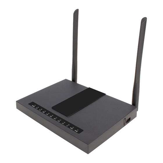
Chapter 1: Product description AC1100MSF Table 1 Features at-a-glance Port/Model AC1100MSF Picture Speed limit NAT Ethernet 5* RJ45 interface 10/100M/1000M T.30, T.38 Fax Wi-Fi 2.4G 2T2R (300Mbps) 2.4G 2T2R(300Mbps) 2.4G 2T2R (300Mbps) 5G 2T2R (867Mbps) 5G 2T2R (867Mbps) Voice Code G.711 (A-law, U-law), G.729A/B, G.723, G.722 (Wide band) -
Page 16: Led Indicators And Interfaces
Chapter 1 Product description LED Indicators and Interfaces Table 2 LED Indicators AC1100MSF Status Explanation on Green System is powered on Power System is powered off on Green System runs normally System Blinking Green System trouble System is powered off... -
Page 17: Table 3 Interfaces
Chapter 1 Product description Table 3 Interfaces AC1100MSF Interface Description POWER Connector for a power adapter Phone1/2 ATA Analog phone connector Connector for accessing the Internet LAN 1/2/3/4 Connectors for local networked devices COMBO Connect the optical module RESET Restore the factory settings button, press and hold the device after 5s to restore the... - Page 18 5. Check the Power, WAN, and LAN LED to confirm network connectivity. Warning Please do not attempt to use unsupported power adapters and do not remove power during configuring or updating the device. Using other power adapters may damage the AC1100MSF and will void the manufacturer warranty.
- Page 19 Chapter 1 Product description Warning Changes or modifications not expressly approved by the party responsible for compliance can void the user’s authority to operate the equipment. This equipment has been tested and found to comply with the limits for a Class B digital device, pursuant to Part 15 of the FCC Rules.
-
Page 20: Voice Prompt
Chapter 1 Product description Voice Prompt The devices may be configured by navigating the unit’s voice menu. By using your phone and dialing a sequence of commands, the device may be configured for operation. Each device configuration section may be accessed by entering a certain operation code, as shown below. Table 4 Voice Menu Setting Options Operation Menu Navigation... - Page 21 Chapter 1 Product description 1. Pick up phone and press “****” to start IVR 2. Choose “2”, and The router reports current WAN Port IP Address 3. Input the new WAN port IP address and press “#” key: 4. Use “*” to replace “.”, for exampleuser can input 192*168*20*168 to set WAN Port IP the new IP address 192.168.20.168 Address...
- Page 22 Chapter 1 Product description 1. Pick up phone and press “****” to start IVR 2. Choose “5”, and the router reports current DNS 3. Input the new DNS and press # key: 4. Use “*” to replace “.”, user can input 192*168*20*1 to set the new gateway 192.168.20.1.
- Page 23 Chapter 1 Product description 1. Pick up phone and press “****” to start IVR 2. Choose “5”, and the router reports “WAN Port Login” WAN Port 3. Prompt "Please enter password", the method of inputting password is same as Login operation 1.
- Page 24 If in DHCP mode, please make sure that a DHCP server is available in your existing broadband connection to which WAN port of AC1100MSF is connected. 7. The default LAN port IP address of router is 192.168.11.1 and this address should not be assigned to the WAN port IP address of router in the same network segment of LAN port.
-
Page 25: Chapter 2 Configuring Basic Settings
Chapter 2 Configuring Basic Setting Chapter 2 Configuring Basic Settings This chapter covers: • Two-Level Management • Web Management Interface • Configuring • Making a Call... -
Page 26: Two-Level Management
This section explains how to setup a password for an administrator or user and how to adjust basic and advanced settings. The AC1100MSF supports two-level management: (1) administrator and user. For administrator mode operation, please type “admin/admin” on Username/Password and click Login button to begin configuration. - Page 27 Chapter 2 Configuring Basic Settings Note If you are unable to access the web configuration, please see Chapter 5: Troubleshooting Guide for more information. The web management interface automatically logs out the user after 5 minutes of inactivity. Logging in from the WAN port Ensure your PC is connected to the router’s WAN port correctly.
-
Page 28: Web Management Interface Details
Chapter 2 Configuring Basic Settings Web Management Interface Details Table 5 Web management interface Field Name Descripti Top Navigation bar Click an option in Top Navigation bar (area marked as “1”). Multiple options in the Sub-navigation bar are displayed Sub-navigation bar Click the Sub-navigation bar to choose a configuration page (area marked as “2”) Parameter configuration... -
Page 29: Setting The Time Zone
Chapter 2 Configuring Basic Settings After changing the parameters need to click this button to save & apply, modify the parameters immediately take effect. Any time changes are made click "Save" to confirm and save the changes. On click of “Save” button, a red message will be displayed as shown below to notify a reboot. -
Page 30: Configuring An Internet Connection
Chapter 2 Configuring Basic Settings Configuring an Internet Connection From the Network > WAN page, WAN connections may be inserted or deleted. For more information on Internet Connection setting, see Table 10below. Table 7 Configuring an internet connection Field Name Description Connect Name Use keywords to indicate WAN port service model (the parameters are defined... - Page 31 Chapter 2 Configuring Basic Settings VLAN ID Note Multiple WAN connections may be created with the same VLAN ID DNS Mode Select DNS mode, options are Auto and Manual: When DNS mode is Auto, the device under LAN port will automatically obtains the preferred DNS and alternate DNS.
-
Page 32: Setting Up Wireless Connections
Multiple SSID 1 - 4, configure up to 4 unique SSIDs Enabled: The device SSID is broadcast at regular intervals Disabled: The device SSID is not broadcast at regular intervals, broadcast(SSID) disallowing wi-fi clients from automatically connecting to the AC1100MSF... - Page 33 Chapter 2 Configuring Basic Settings Enabled: Devices connected to the router are isolated from one another on virtual AP Isolation networks Disabled: Devices connected to the router are visible on the network to each other Enabled: Devices connected to the router via one of the Multiple SSIDs are isolated MBSSID AP Isolation from one another on virtual networks Disabled: Devices connected to the router via one of the Multiple SSIDs are visible on...
-
Page 34: Table 9 Wireless Security Web Page
Chapter 2 Configuring Basic Settings Encryption Open Wireless/Wireless Security webpage to configure custom security parameters. Table 9 Wireless Security web page Field Name Description SSID Choice Choose the SSID from the drop-drown list for which security will be configured Select an appropriate encryption mode to improve the security and privacy of your wireless data packets. -
Page 35: Configuring Session Initiation Protocol (Sip)
Chapter 2 Configuring Basic Settings Configuring Session Initiation Protocol (SIP) SIP Accounts The device has 2 FXS ports to make SIP (Session Initiation Protocol) calls. Before registering, the device user should have a SIP account configured by the system administrator or provider. See the section below for more information. -
Page 36: Table 11 Registration Status
Chapter 2 Configuring Basic Settings Note Upon the following dialogue: Please press button to make changes effective. Viewing the Registration Status Table 11 Registration status Procedure To view the SIP account status of device, open the Status webpage and view the value of registration status. -
Page 37: Making A Call
Chapter 2 Configuring Basic Settings Making a Call Calling phone or extension numbers To make a phone or extension number call: • Both ATA and the other VoIP device (i.e., another ATA or other SIP products) must have public IP addresses, or •... - Page 38 Chapter 2 Configuring Basic Settings Blind Transfer Assume that call party A and party B are in conversation. Party A wants to Blind Transfer B to C: Party A dials “*78” to get a dial tone, then dials party C’s number, and then press immediately key # (or wait for 4 seconds) to dial out.
-
Page 39: Chapter 3: Web Interface
Chapter 3 Web Interface Chapter 3: Web Interface This chapter guides users to execute advanced (full) configuration through admin mode operation. This chapter covers: • Login • Status • Network and Security • Wireless • • FXS1 • FXS2 • Security •... -
Page 40: Login
Chapter 3 Web Interface Login Table 12 Login details Procedure 1. Connect the LAN port of the router to your PC an Ethernet cable 2. Open a web browser on your PC and type http://192.168.1.1. 3. Enter Username admin and Password admin. 4. -
Page 41: Status
Chapter 3 Web Interface Status Table 13 Status Page... - Page 42 Chapter 3 Web Interface...
- Page 43 Chapter 3 Web Interface...
- Page 44 Chapter 3 Web Interface Description This webpage shows the status information about the Product, Network, and System including Product Information, SIP Account Status, FXS Port Status, Network Status. Wireless Info and System Status...
-
Page 45: Table 14 Internet
Chapter 3 Web Interface Network and Security You can configure the WAN port, LAN port, DDNS, Multi WAN, DMZ, Port Forward and other parameters in this section of the web management interface. This page allows you to set WAN configuration with different modes. Use the Connection Type drop down list to choose one WAN mode and then the corresponding page will be displayed. - Page 46 Chapter 3 Web Interface DHCP The Router has a built-in DHCP server that assigns private IP address to each local client. The DHCP feature allows to the router to obtain an IP address automatically from a DHCP server. In this case, it is not necessary to assign an IP address to the client manually.
- Page 47 Chapter 3 Web Interface PPPoE PPPoE stands for Point-to-Point Protocol over Ethernet. It relies on two widely accepted standards: PPP and Ethernet. It connects users through an Ethernet to the Internet with a common broadband medium, such as a single DSL line, wireless device or cable modem. All the users over the Ethernet can share a common connection. PPPoE is used for most of DSL modem users.
- Page 48 Chapter 3 Web Interface Confirm Password Enter your PPPoE password again Service Name Enter a service name for PPPoE authentication. If it is left empty, the service name is auto detected. Operation Mode Select the mode of operation, options are Keep Alive, On Demand and Manual: When the mode is Keep Alive, the user sets the 'keep alive redial period' values range from 0 to 3600s, the default setting is 5 minutes;...
-
Page 49: Table 17 Bridge Mode
Chapter 3 Web Interface Bridge Mode Bridge Mode under Multi WAN is different with traditional bridge setting. Bridge mode employs no IP addressing and the device operates as a bridge between the WAN port and the LAN port. Route Connection has to be built to give IP address to local service on device. - Page 50 Chapter 3 Web Interface DHCP packet from the WAN interface to the LAN interface. Local DHCP service will not allocate IP to clients of LAN port. Local Service Gateway will not forward DHCP packets between LAN and WAN, it also blocks DHCP packets from the WAN port.
-
Page 51: Table 18 Lan Port
Chapter 3 Web Interface LAN Port NAT translates the packets from public IP address to local IP address to forward packets to the proper destination. Table 18 LAN port Field Name Description IP Address Enter the IP address of the router on the local area network. All the IP addresses of the computers which are in the router’s LAN must be in the same network segment with this address, and the default gateway of the computers must be this IP address. - Page 52 Chapter 3 Web Interface DHCP Start Address Enter a valid IP address as a starting IP address of the DHCP server, and if the router’s LAN IP address is 192.168.11.1, starting IP address can be 192.168.11.2 or greater, but should be less than the ending IP address. DHCP End Address Enter a valid IP address as an end IP address of the DHCP server.
-
Page 53: Table 19 Dhcp Server Settings
Chapter 3 Web Interface DHCP Server The router has a built-in DHCP server that assigns private IP address to each local client. DHCP stands for Dynamic Host Configuration Protocol. The router, by factory default acts a DHCP server for your network so it automatically dispatches related IP settings to any local user configured as a DHCP client. -
Page 54: Table 21 Lte
Chapter 3 Web Interface Field Name Description Specify the Primary DNS address provided by your ISP. If your ISP does not provide it, the router will automatically apply default DNS Server IP address: 202.96.134.33 Primary DNS to this field. Specify the Secondary DNS address provided by your ISP. If your ISP does not provide this address, the router will automatically apply default Secondary DNS Server IP of 202.96.128.86 to this field. - Page 55 Chapter 3 Web Interface Field Name Description Basic Setting LTE Modem Enable Enable the LTE Modem GSM Call Enable Enable the GSM Cal 4G Connection Type Choose the 4G connection method, Auto or Manual The APN default to CMNET Dial Number Username Enter the username Password...
-
Page 56: Table 22 Port Forward
Chapter 3 Web Interface Field Name Description VPN Enable Enable/Disable VPN. If the VPN is enabled, user can select PPTP and L2TP mode VPN. Initial Service IP Enter VPN server IP address. User Name Enter authentication username. Password Enter authentication password. Port Forward Table 22 Port Forward... -
Page 57: Table 23 Vlan
Chapter 3 Web Interface Field Name Description Comment Sets the name of a port mapping rule or comment IP Address The IP address of devices under the LAN port Port Range Set the port range for the devices under the LAN port. (1-65535) Protocol You can select TCP, UDP, TCP &... -
Page 58: Table 24 Dmz
Chapter 3 Web Interface Table 24 DMZ Field Name Description DMZ Enable Enable/Disable DMZ. DMZ Host IP Address Enter the private IP address of the DMZ host. DDNS Table 25 DDNS... -
Page 59: Table 26 Qos
Chapter 3 Web Interface Field Name Description Dynamic DNS Enable DDNS and select the DDNS service provider Provider Account Fill in the DDNS service account Password Fill in the DDNS service account password DDNS URL Fill in the DDNS domain name or IP address Status Check if DDNS is successfully upgraded Table 26 QoS... -
Page 60: Table 27 Port Setting
Chapter 3 Web Interface Port Setting Table 27 Port setting Field Name Description WAN Port speed Nego Auto-negotiation, options are Auto, 100M full, 100M half-duplex, 10M half and full. LAN1~LAN3 Port Speed Auto-negotiation, options are Auto, 100M full, 100M half, 10M half and 10M Nego full. -
Page 61: Table 29 Advance
Comment Advance Table 29 Advance Field Name Description Most Nat connections The largest value which the AC1100MSF can provide Mss Mode Choose Mss Mode from Manual and Auto Mss Value Set the value of TCP AntiDos-p You can choose to enable or prohibit... -
Page 62: Table 30 Basic
Chapter 3 Web Interface Wireless 2.4G Basic Table 30 Basic Field Name Description Radio on/off Select “Radio off” to disable wireless. Select “Radio on” to enable wireless. Wireless connection mode According to the wireless client type, select one of these modes. Default is AP Network Mode Choose one network mode from the drop-down list. - Page 63 Chapter 3 Web Interface SSID It is the basic identity of wireless LAN. SSID can be any alphanumeric or a combination of special characters. It will appear in the wireless network access list. Multiple SSID1~SSID3 The device supports 4 SSIDs. Hidden After the item is checked, the SSID is no longer displayed in the search for the Wi-Fi wireless network connection list...
- Page 64 Chapter 3 Web Interface Enabled: Multiple copies of signals are transmitted to increase the chance of successful delivery Aggregation MSDU (A- Enabled: Allows the device to aggregate multiple Ethernet frames into a single Disabled: STBC is not employed for signal transmission MSDU) 802.11n, thereby improving the ratio of frame data to frame overhead Disabled: No frame aggregation is employed at the router...
-
Page 65: Table 31 Wireless Security
Chapter 3 Web Interface Wireless Security Table 31 Wireless security Field Name Description SSID Choice Choose one SSID from SSID, Multiple SSID1, Multiple SSID2 and Multiple SSID3. Select an appropriate encryption mode to improve the security and privacy of your wireless data packets. -
Page 66: Table 32 Wi-Fi Security Setting
Chapter 3 Web Interface User can configure the corresponding parameters. Here are some common encryption methods: OPENWEP : A handshake way of WEP encryption, encryption via the WEP key: Table 32 Wi-Fi Security Setting Field Name Description Security Mode This is used to select one of the 4 WEP keys, key settings on the clients should be the same with this when connecting. -
Page 67: Table 33 Wpa-Psk
Chapter 3 Web Interface WPA-PSK, the router will use WPA way which is based on the shared key-based . Table 33 WPA-PSK Field Name Description WPA Algorithms This item is used to select the encryption of wireless home gateway algorithms, options are TKIP, AES and TKIPAES. -
Page 68: Table 35 Wireless Access Policy
Chapter 3 Web Interface WPA-PSK/WPA2-PSK WPA/WPA2 security type is actually a simplified version, which is based on the WPA shared key mode, higher security setting is also relatively simple, suitable for ordinary home users and small businesses. Wireless Access Policy: Table 35 Wireless Access Policy Field Name Description... - Page 69 Chapter 3 Web Interface Table 36 WMM Description WMM (Wi-Fi Multi-Media) is the QoS certificate of Wi-Fi Alliance (WFA). This provides you to configure the parameters of wireless multimedia; WMM allows wireless communication to define a priority according to the home gateway type. To make WMM effective, the wireless clients must also support WMM.
-
Page 70: Table 37 Wds
Chapter 3 Web Interface Table 37 WDS Description WDS stands for Wireless Distribution System, enabling WDS access points to be interconnected to expand a wireless network. WPS (Wi-Fi Protected Setup) provides easy procedure to make network connection between wireless station and wireless access point with the encryption of WPA and WPA2. It is the simplest way to build connection between wireless network clients and wireless access point. - Page 71 Chapter 3 Web Interface Table 38 WPS Field Name Description WPS Config Enable/Disable WPS function WPS Summary WPS Current Status Display the current status of WPS Display the configure the status information of WPS WPS Configured Display WPS SSID WPS SSID WPS Progress WPS Mode PIN:Enter the PIN code of the wireless device which accesses to this LAN in the...
-
Page 72: Table 39 Station Info
Chapter 3 Web Interface WPS shows status in three ways: WPS Status WSC: Idle WSC: Start WSC process (begin to send messages) WSC: Success; this means clients have accessed the AP successfully Station Info Table 39 Station info Description This page displays information about the current registered clients’ connections including operating MAC address and operating statistics. -
Page 73: Table 40 Advanced
Chapter 3 Web Interface Advanced Table 40 Advanced Field Name Description BG Protection Mode Select G protection mode, options are on, off and automatic. Beacon Interval The interval of sending a wireless beacon frame, within this range, it will send a beacon frame for the information of the surrounding radio network. - Page 74 Chapter 3 Web Interface RTS Threshold Specify the packet RTS threshold, when the packet exceeds this value, the router will send RTS to the destination site consultation TX Power Define the transmission power of the current AP, the greater it is, the stronger the signal is Short Preamble Choose enable or disable...
- Page 75 Chapter 3 Web Interface Wireless 5G Please refer to the wireless 2.4G.
-
Page 76: Table 41 Sip Settings
Chapter 3 Web Interface SIP Settings Table 41 SIP settings Field Name Description SIP T1 The minimum scale of retransmission time Max Forward SIP contains Max Forward message header fields used to limit the requests for forwards SIP Reg User Agent Name The agent name of SIP registered user Max Auth The maximum number of retransmissions... -
Page 77: Table 42 Voip Qos
Encryption Message) Service Type Choose the server type NAT Traversal Enable/Disable NAT Traversal The AC1100MSF supports STUN Traversal; if user wants to traverse NAT/Firewall, select the STUN STUN Server Add the correct STUN service provider IP address Address NAT Refresh... -
Page 78: Table 43 Parameters And Settings
Chapter 3 Web Interface Dial Plan Parameters and Settings Table 43 Parameters and settings Field Name Description Dial Plan Enable/Disable dial plan Line Set the line Digit Map Enter the sequence used to match input number The syntactic, please refer to the following Dial Plan Syntactic Action Choose the dial plan mode from Deny and Dial Out. - Page 79 Chapter 3 Web Interface...
-
Page 80: Table 44 Adding One Dial Plan
Chapter 3 Web Interface Adding one Dial Plan Table 44 Adding one dial plan Description Step 1. Enable Dial Plan Step 2. Click Add button, and the configuration table Step 3. Fill in the value of parameters Step 4. Press OK button to end configuration... -
Page 81: Table 45 Dial Plan
Chapter 3 Web Interface Dial Plan Syntactic Table 45 Dial Plan String Description 0 1 2 3 4 5 6 7 8 9 * # Allowed characters Lowercase letter “x” stands for one legal character To match one character form sequence. For example: [sequence] [0-9]: match one digit from 0 to 9 [23-5*]: match one character from 2 or 3 or 4 or 5 or *... -
Page 82: Table 46 Blacklist
Chapter 3 Web Interface Blacklist In this page, user can upload or download blacklist file, and can add or delete or edit blacklist one by one. Table 46 Blacklist Description Click to select the blacklist file and to upload it to device; Click to save the blacklist file to your local computer. -
Page 83: Table 47 Call Log
Chapter 3 Web Interface Call Log To view the call log information such as redial list , answered call and missed call Table 47 Call log Redial List... - Page 84 Chapter 3 Web Interface Answered Calls Missed Calls...
-
Page 85: Table 48 Sip Account - Basic
Chapter 3 Web Interface FXS1 SIP Account Basic Set the basic information provided by your VOIP Service Provider, such as Phone Number, Account, password, SIP Proxy and others. Table 48 SIP Account - Basic Field Name Description Line Enable Enable/Disable the line. Enable/Disable PEER to PEER. -
Page 86: Table 49 Audio Configuration
Chapter 3 Web Interface Outbound Port Outbound Proxy’s Service port, default is 5060 Backup Outbound Port Backup Outbound Proxy’s Service port, default is 5060 Display Name The number will be displayed on LCD Phone Number Enter telephone number provided by SIP Proxy Account Enter SIP account provided by SIP Proxy Password... -
Page 87: Table 50 Supplementary Service
Chapter 3 Web Interface G.723 Coding Speed Choose the speed of G.723 from 5.3kbps and 6.3kbps Packet Cycle The RTP packet cycle time, default is 20ms Silence Supp Enable/Disable silence support Echo Cancel Enable/Disable echo cancel. By default, it is enabled Auto Gain Control Enable/Disable auto gain T.38 Enable... -
Page 88: Table 51 Advanced
Chapter 3 Web Interface Voice Mailbox Fill in the voice mailbox phone number, Asterisk platform, for example, its default voice Numbers mail is *97 VMWI Serv Enable/Disable VMWI service Enable/Disable DND (do not disturb) If enable, any phone call cannot arrive at the device; default is disable Enter the speed dial phone numbers. - Page 89 Chapter 3 Web Interface Field Name Description Domain Name Type If or not use domain name in the SIP URI. Carry Port Information If or not carry port information in the SIP URI. Signal Port The local port of SIP protocol, default is 5060. DTMF Type Choose the DTMF type from Inbound, RFC2833 and SIP INFO.
-
Page 90: Table 52 Volume Settings
Chapter 3 Web Interface Dial Prefix The number will be added before your telephone number when making calls. User Type Choose the User Type from IP and Phone. Hold Method Choose the Hold Method from ReINVITE and INFO. Request-URI User Check Enable/Disable the user request URI check. -
Page 91: Table 53 Regional
Chapter 3 Web Interface Regional Table 53 Regional Field Name Description Tone Type Choose tone type form China, US, Hong Kong and so on Dial Tone Dial Tone Busy Tone Busy Tone Off Hook Warning Tone Off Hook warning tone Ring Back Tone Ring back tone Call Waiting Tone... -
Page 92: Table 54 Features And Call Forward
Chapter 3 Web Interface Features and Call Forward Table 54 Features and call forward Field Description Name All Forward Enable/Disable forward all calls Features Busy Forward Enable/Disable busy forward. No Answer Forward Enable/Disable no answer forward. All Forward Set the target phone number for all forward. The device will forward all calls to the phone number immediately when there is an incoming call. - Page 93 Chapter 3 Web Interface Transfer key code Call forwarding signatures, default is *98. IVR key code Signatures of the voice menu, default is ****. R key enable Enable/Disable R key way call features. R key cancel code Set the R key cancel code, options range from R1 to R9, default value is R1.
-
Page 94: Table 55 Miscellaneous
Chapter 3 Web Interface Miscellaneous Table 55 Miscellaneous Field Name Description Codec Loop Current Set off-hook loop current, default is 26. Impedance Matching Set impedance matching, default is US PBX,Korea,Taiwan(600). CID service Enable/Disable displaying caller ID; If enable, caller ID is displayed when there is an incoming call or it won’t be displayed. - Page 95 Chapter 3: Web Interface FXS2 The settings of FXS2 are the same as FXS1. See FXS1 on page 74.
-
Page 96: Table 56 Filtering Setting
Chapter 3 Web Interface Security Filtering Setting Table 56 Filtering setting Field Name Description Filtering Enable/Disable filter function Default Policy Choose to drop or accept filtered MAC addresses Mac address Add the Mac address filtering Dest IP address Destination IP address Source IP address Source IP address Protocol... -
Page 97: Table 57 Content Filtering
Chapter 3 Web Interface Content Filtering Table 57 Content filtering... - Page 98 Chapter 3 Web Interface Field Name Description Filtering Enable/Disable content Filtering Default Policy The default policy is to accept or to prohibit filtering rules Current Webs URL Filters List the URL filtering rules that already existed (blacklist) Delete/Cancel You can choose to delete or cancel the existing filter rules Add a URL Filter Add URL filtering rules Add/Cancel...
-
Page 99: Table58 Advance Nat
Chapter 3 Web Interface Application Advance NAT Table58 advance NAT Enable/Disable these function(FTP/SIP/H323/PPTP/L2TP/IPSec). UPnP UPnP (Universal Plug and Play) supports zero-configuration networking, and can automatically discover a variety of networked devices. When UPnP is enabled, the connected device is allowed to access the network, obtain an IP address, and convey performance information. -
Page 100: Table 60 Igmp
Chapter 3 Web Interface IGMP Multicast has the ability to send the same data to multiple devices. IP hosts use IGMP (Internet Group Management Protocol) report multicast group memberships to the neighboring routers to transmit data, at the same time, the multicast router use IGMP to discover which hosts belong to the same multicast group. -
Page 101: Table 61 Disk Management
Chapter 3 System planning Storage Storage Disk Management This page is used to manage the USB storage device. Table 61 Disk Management Field Name Description Adding files to the USB storage device Delete Remove the USB storage device file Remove Disk Transfer files within a USB storage device Format Format the USB storage device... -
Page 102: Table 62 Ftp Setting
Chapter 3 System planning Storage FTP Setting Table 62 FTP Setting Field Name Description FTP Server Enable/Disable FTP server FTP Server Name Set the FTP server name Anonymous Login If or not support anonymous login FTP Port Set FTP server port number Max. -
Page 103: Table 63 Smb Setting
Chapter 3 System planning Storage Smb Setting Table 63 Smb setting Field Name Description SAMBA Server Enable/Disable SAMBA server Workgroup Enter the working group NetBIOS Name Network basic input/output system name Add a shared file Edit Edit a shared file Delete a shared file Add a shared file Edit... -
Page 104: Table 64 Save Config File
Chapter 3 System planning Storage Administration The user can manage the device in these webpages; you can configure the Time/Date, password, web access, system log and associated configuration TR069. Management Save config file Table 64 Save Config File Field Name Description Config file upload and Upload: click on browse, select file in the local, press the upload button to... -
Page 105: Table 65 Administrator Settings
Chapter 3 System planning Storage Administrator settings Table 65 Administrator settings Field Name Description User type Choose the user type from admin user and normal user and basic user New User Name You can modify the user name, set up a new user name New Password Input the new password Confirm Password... -
Page 106: Table 66 Ntp Settings
Chapter 3 System planning Storage Web Idle timeout Set the Web Idle timeout time. The webpage can be logged out after Web Idle Timeout without any operation. Allowed Remote IP(IP1,IP2,...) Set the IP from which a user can login the device remotely. Telnet Port Set the port value which is used to telnet to the device. -
Page 107: Table 67 Daylight Saving Time
Chapter 3 System planning Storage Secondary NTP Server Options for NTP server's IP address or domain name NTP synchronization NTP synchronization cycle, cycle time can be 1 to 1440 minutes in any one, the default setting is 60 minutes Daylight Saving Time Table 67 Daylight Saving Time Procedure Step 1. -
Page 108: Table 68 System Log Setting
Chapter 3 System planning Storage System Log Setting Table 68 System log Setting Field Name Description Syslog Enable Enable/Disable syslog function Syslog Level Select the system log, there is INFO and Debug two grades, the Debug INFO can provide more information Remote Syslog Enable Enable/Disable remote syslog function Remote Syslog server Add a remote server IP address. -
Page 109: Table 70 Factory Defaults
Chapter 3 System planning Storage Factory Defaults Table 70 Factory Defaults Description Click Factory Default to restore the residential gateway to factory settings. Firmware Upgrade Table 71 Firmware upgrade Description 1. Click Choose File 3. Press to start upgrading... -
Page 110: Table 72 Lte Upgrade
Chapter 3 System planning Storage LTE Upgrade Table 72 LTE upgrade Description You can fill in LTE download URL, upgrade LTE Scheduled Tasks Table 73 Scheduled Tasks... - Page 111 Chapter 3 System planning Storage Field Name Description Scheduled Wi-Fi Enable Enable / Disable Timed WI-FI SSID This is not optional Scheduled Mode Choose work mode, weekly / days Wi-Fi work time Set the WI-FI duty cycle Apply and Cancel After modifying the parameters, select Apply, or Cancel Scheduled Reboot Scheduled Reboot...
-
Page 112: Table 74 Provision
Chapter 3 System planning Storage Table 74 Provision Field Name Description Enable provision or not. Provision Enable Enable resync after restart or not Resync on Reset Resync Random Set the maximum delay for the request of synchronization file. The default is Delay(sec) Resync Periodic(sec) If the last resync was failure, The router will retry resync after the “Resync... -
Page 113: Table 75 Firmware Upgrade
Chapter 3 System planning Storage Config File Name It is used for In-house provision mode only. When use TFTP with option 66 to realize provisioning, user must input right configuration file name in the webpage. When disable Option 66, this parameter has no effect. Profile Rule URL of profile provision file Note that the specified file path is relative to the TFTP server’s virtual... -
Page 114: Table 76 Snmp
Chapter 3 System planning Storage SNMP Table 76 SNMP Field Name Description SNMP Service Enable or Disable the SNMP service Trap Server Address Enter the trap server address for sending SNMP traps Read Community Name String value that is used as a password to request information via SNMP from the device Write Community Name String value that is used as a password to write configuration values to the... -
Page 115: Table 77 Tr069
Chapter 3 System planning Storage TR-069 TR-069 provides the possibility of auto configuration of internet access devices and reduces the cost of management. TR-069 (short for Technical Report 069) is a DSL Forum technical specification entitled CPE WAN Management Protocol (CWMP). It defines an application layer protocol for remote management of end-user devices. - Page 116 Chapter 3 System planning Storage Periodic Inform Enable Enable the function of periodic inform or not. By default, it is Enabled Periodic Inform Interval Periodic notification interval with the unit in seconds. The default value is 3600s Connect Request parameters User Name The username used to connect the TR069 server to the DUT Password...
-
Page 117: Table 78 Diagnosis
Chapter 3 System planning Storage Diagnosis In this page, user can do packet trace, ping test and traceroute test to diagnose the device’s connection status. Table 78 Diagnosis... - Page 118 Chapter 3 System planning Storage Description 1. Packet Trace Users can use the packet trace feature to intercept packets which traverse the device. Click the Start button to start home gateway tracking and keep refreshing the page until the message trace shows to stop, click the Save button to save captured packets.
-
Page 119: Operating Mode
Chapter 3 System planning Storage Operating Mode Table 79 Operating mode Description Choose the Operation Mode as Basic Mode or Advanced Mode. -
Page 120: System Log
Chapter 3 System planning Storage System Log Table 80 System log Description If you enable the system log in Status/syslog webpage, you can view the system log in this webpage. Logout Table 81 Logout Description Press the logout button to logout, and then the login window will appear. Reboot Press the button to reboot the device. -
Page 121: Chapter 4 Ipv6 Address Configuration
Chapter 4 IPv6 address configuration Chapter 4 IPv6 address configuration The router devices support IPv6 addressing. This chapter covers: • Introduction • IPv6 Advance • Configuring IPv6 • Viewing WAN port status • IPv6 DHCP configuration for LAN/WLAN clients • LAN DHCPv6... -
Page 122: Introduction
Chapter 4 IPv6 address configuration Introduction DHCPv6 protocol is used to automatically provision/configure IPv6 capable end points in a local network. In addition to acquiring an IPv6 IP address for the WAN interface and its associated LAN/WLAN clients, the devices are also capable of prefix delegation. The Routers devices support the following types of modes of IPv6 addresses: •... -
Page 123: Ipv6 Advance
Chapter 4 IPv6 address configuration IPv6 Advance To enable IPv6 functionality: Navigate to Network > IPv6 Advanced page. Select Enable from the IPv6 Enable drop-down list. Click Save. Table 83 Enabling IPv6 Configuring IPv6 Configuring Statefull IPv6 1. Navigate to Network > IPv6WAN page. The following window is displayed:... -
Page 124: Table 84 Configuring Statefull Ipv6
Chapter 4 IPv6 address configuration Table 84 Configuring Statefull IPv6 Field Name Description Connection Type Select connection type DHCPv6 Address Settings Set it to statefull mode. Prefix Delegation Select Enable. -
Page 125: Table 85 Configuring Stateless Ipv6
Chapter 4 IPv6 address configuration Configuring Stateless IPv6 Table 85 Configuring Stateless IPv6 Field Name Description Connection Type Select connection type DHCPv6 Address Settings Set it to stateless mode Prefix Delegation Select Enable... -
Page 126: Viewing Wan Port Status
Chapter 4 IPv6 address configuration Viewing WAN port status To view the status of WAN port: Navigate to Status page. IPv6 DHCP configuration for LAN/WLAN clients Wired and wireless clients connected to the Routers can obtain their IPv6 addresses based on how the LAN s ide DHCPv6 parameters are configured. -
Page 127: Lan Dhcpv6
Chapter 4 IPv6 address configuration LAN DHCPv6 When IPv6 is enabled, the LAN/WLAN clients of Routers can be configured to receive IPv6 addresses from locally configured IPv6 pool or from an external DHCPv6 server. To enable LAN DHCPv6 service:... -
Page 128: Chapter 5 Troubleshooting Guide
Chapter 5 Troubleshooting Guide This chapter covers: • Configuring PC to get IP Address automatically • Cannot connect to the Web GUI • Forgotten Password... -
Page 129: Configuring Pc To Get Ip Address Automatically
Chapter 5 Troubleshooting Guide Configuring PC to get IP Address automatically Follow the below process to set your PC to get an IP address automatically: Step 1 : Click the “Start” button Step 2 : Select “control panel”, then double click “network connections” in the “control panel” Step 3 : Right click the “network connection”... -
Page 130: Cannot Connect To The Web
Chapter 5 Troubleshooting Guide Cannot connect to the Web Solution: • Check if the Ethernet cable is properly connected. • Check if the URL is correct. The format of URL is: http:// the IP address. • Check on any other browser apart from Internet explorer such as Chrome. •... -
Page 131: Chapter 6: Appendix A - Auto Provisioning Manual
Appendix A Auto-Provisioning Manual AC1100MSF... - Page 132 Table of Contents Introduction ...................... 120 Configure Provisioning Parameters .............. 121 Enable Provisioning ..................121 Syntax of Profile Rule and Upgrade Rule ............122 Macro Expansion ..................... 123 Provisioning ..................... 124 Provision with HTTP ..................124 Provision with DHCP and TFTP ..............125 Provisioning Examples ...................
-
Page 133: Introduction
Auto-Provisioning of ReadyNet Router ATAs Introduction This document is targeted to developers and system integrators who intend to include support for the ReadyNet ATAs in their VoIP provisioning systems. It provides details for auto- provisioning ReadyNet!"#$%&"' with one or more ATA ports. Auto-provisioning is supported via TFTP, HTTP and HTTPS as well as DHCP Option 66, allowing for true zero-touch remote provisioning. - Page 134 Parameter Name Description Default Value Provision Enable Enable or disable the Provision functions. Resync on Reset Triggers a resync after every reboot except for reboot caused by parameter updates and firmware upgrades. Resync Random Delay The maximum value for a random time interval that the 40 seconds device waits before making its initial contact with the provisioning server.
-
Page 135: Syntax Of Profile Rule And Upgrade Rule
The table below describes the various firmware upgrade parameters and provides their default values. Parameter Description Default Value Enable Upgrading Enables firmware upgrade operations independently of Enable resync actions The upgrade retry interval (in seconds) applied in Upgrade Error Retry 3600 seconds case of upgrade failure. -
Page 136: Macro Expansion
acro Expansion Macro expansion can be used with the parameters ‘Profile Rule’!and ‘Upgrade Rule’. The table below list the macros variables and to what they expand. Macro Name Expansion The form $$ expands to a single $ character. The form $$MAU expands to $00019F16B1B2. The form $MAU expands to 00019F16B1B2. -
Page 137: Provisioning
Provisioning Provision with HTTP Begin by resetting a ReadyNet router to factory defaults. Install an HTTP server on the WAN side of the router. In the DocumentRoot of the HTTP server, create a directory named ‘prov’ for provisioning files. So if the path to the DocumentRoot is /var/www/html, the path to the directory for the provisioning files will be /var/www/html/prov . -
Page 138: Provision With Dhcp And Tftp
4) Log into the ReadyNet router, navigate to Administration -> Provision and set the ‘Option 66’ field to Disable and in the Profile Rule field enter: http://HTTP_SERVER/prov/a.cfg . 5) Click save and then do a reboot. 6) When the device boots and its WAN interface is up, it will retrieve the file located at Profile Rule. The ATA will reboot to apply the new parameters. -
Page 139: Provisioning Examples
DBID_RESYNC_PERIODIC=60 DBID_PRV_OPTION66_ENABLED=0 DBID_PROFILE_RULE=http://172.16.8.25/prov/$MAU.conf Note: We change DBID_RESYNC_PERIODIC to 60 seconds only during testing and development. 10) In the prov directory of the HTTP server create a file named 00019F16XXXX.conf, replacing XX:XX in the file name to match the WAN MAC address of the router. DBID_SUPER_WEB_PASSWORD=newpass2 So if the WAN MAC address is 00:01:9F:16:00:01, the file would be named, ‘00019F160001.conf’. -
Page 140: Table 15 Dhcp
mwan_primary_dns=8.8.8.8 Provisioning LAN Parameters This remote provisioning example file changes the network parameters on the LAN side of the router. In addition, this file changes the username and passwords of the two administrative access levels of the web interface of the router. lan_ipaddr=192.168.88.1 lan_netmask=255.255.255.0 dhcpGateway=192.168.88.1... -
Page 141: Table 16 Pppoe
Appendix B Network Parameters Parameter Valid Values Description mwanConnectionMode DHCP This parameter defines the WAN connection method. It can STATIC be one of the following; Static, DHCP or PPPOE. PPPOE mdns_mode With the default setting of 0, the device will use the DNS server provided by the DHCP server. -
Page 142: Lan Network Parameters
LAN Network Parameters Parameter Valid Values Description When in natEnabled is set to NAT, the router operates natEnabled as a router and when set to Bridge, all network Bridge interfaces are bridged. lan_ipaddr IP Address This parameter sets the IP address of the LAN interface when natEnabled is set to NAT. -
Page 143: Sip Parameters
SIP Parameters These parameters configure the SIP settings and correspond to the settings seen on the ‘SIP Account’!menu of the web interface. Parameter Description DBID_DNSSRV_DOMAIN This parameter defines the ‘Proxy Server’ for the SIP account. DBID_SIP_OUTBOUND_PORT This parameter defines the ‘Proxy Port’. The default port is 5060. -
Page 144: Administration Parameters
Administration Parameters Parameter Description BasicUser useradmin This parameter defines a web login username of type ‘Basic’. BasicPass admin This parameter defines the password for BasicUser. NormalUser user This parameter defines a web login username of type ‘Normal’. DBID_NORMAL_WEB_PASSWORD user This parameter defines the password for NormalUser. -
Page 145: Provisioning Parameters
Provisioning Parameters Parameter Default Description DBID_PROVISION_ENABLED The default value for this parameter is 1 which enables provisioning for the device. DBID_RESYNC_ON_RESET The default value for this parameter is 1 which triggers a resync after every reboot except for reboot caused by parameter updates and firmware upgrade. -
Page 146: Default Provisioning Template File
Default Provisioning Template File mwanConnectionMode=DHCP dhcpDnsMode=Auto mwan_primary_dns= mwan_secondary_dns= mwan_ipaddr= mwan_netmask= wan_gateway= wan_pppoe_user= wan_pppoe_pass= wan_pppoe_opmode=KeepAlive wan_pppoeoptime=5 wan_vid=2 natEnabled=1 lan_ipaddr=192.168.11.1 lan_netmask=255.255.255.0 dhcpEnabled=1 dhcpStart=192.168.11.2 dhcpEnd=192.168.11.24 dhcpGateway=192.168.11.1 dhcpDnsMode=Auto dhcpPriDns=192.168.11.1 dhcpSecDns=8.8.8.8 dhcpLease=86400 lan_vid=1 DBID_DNSSRV_DOMAIN= DBID_SIP_OUTBOUND_PORT=5060 DBID_SIP_SERVER_HOST_NAME= DBID_SIP_SERVER_PORT=5060 DBID_ALTER_SIP_SERVER_HOSTNAME= DBID_ALTER_SIP_SERVER_PORT=5060 DBID_SIP_DIS_NAME= DBID_SIP_PHONE_NUM= DBID_SIP_ACCOUNT= DBID_SIP_PASSWORD= DBID_SIP_TOS=0 DBID_RTP_TOS=0 DBID_DATA_TOS=0 sip_vid=2 rtp_vid=2... - Page 147 DBID_RESYNC_PERIODIC=3600 DBID_RESYNC_RETRY_DELAY=3600 DBID_RESYNC_DELAY=14400 DBID_RESYNC_AFTER_UPGRADE=1 DBID_PRV_OPTION66_ENABLED=1 DBID_PRV_CONFIGFILE=QX202.cfg DBID_PROFILE_RULE= DBID_UPGRADE_ENABLED=0 DBID_UPGRADE_RETRY_DELAY=3600 DBID_UPGRADE_RULE=...
Need help?
Do you have a question about the AC1100MSF and is the answer not in the manual?
Questions and answers