Advertisement
Quick Links
www.InvisionTechnology.co.uk
Parts List:
6
M4
Severe personal injury and property damage can result from improper installation or assembly. Please read the following warning carefully before beginning.
•
If you do not understand the instructions or have any concerns or questions please contact us or a competent installer.
•
Do not install or assemble if the product or hardware is damaged or missing. If you require replacement parts, please contact us at Invision for assistance
•
This product fits most 17"-27" LCD/monitors to a maximum weight of 6.5kg (14.3lb)
•
Do not use this product for other than the original design purpose
•
This product contains moving parts, please use with caution
•
This product is designed for indoor use only, use of this product outdoors could lead to product failure and severe personal injury
•
When installing monitor take care not to damage electrical wiring or power source
•
Important - mains and data cables must be free from twisting and/or shearing
•
The manufacturer disclaims any liability for the modifications, improper installation or installation over the specified weight range. The manufacturer will not be liable for any damages arising from the use of, or inability to use the product
•
We reserve the right to modify or alter instructions. No modification or alteration with formal notice.
•
If sketches and images are different from parts and components received, please base on actual delivered parts.
Lets Get Started!
If you require assistance please contact us at: help@InvisionTechnology.co.uk
English
Invision NV100
Non VESA Display Adaptor
Instruction Manual
Recommended Screen Sizes 17" - 27"
Display Thickness 30mm - 75mm
Load Capacity 6.5kg (14.3lbs)
To receive large format PDF instructions please
email help@InvisionTechnology.co.uk
Important:
1. Check the box contains all the items in the Parts List.
2. Check the monitor weight & VESA measurement, monitor
arm must have VESA 75x75mm
3. Please read the instructions fully and plan how to mount
your monitor.
4. You will need: A Phillips screw driver, pliers or pipe grips
Tools List:
WARNING!
1
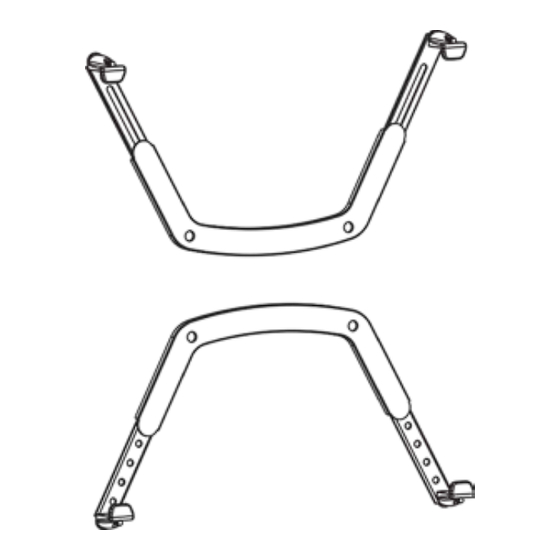
Step 1 - Pre-assembling screen adapters
1. Attach the slotted extension arms, part (C) to upper arm part (A) using the nut and washers I & K see
diagram A. Use spanner provided to tighten up, leave slightly loose so slotted extension arm can slide to
suit screen height, please remember to tighten fully when finished.
2. Attach lower extension arms parts (D) to lower arm , using the hole which suits your screen size, then
using nut and washer I & K fully tighten with spanner provided see Diagram B. (this can be adjusted after
installation if needed)
Tip:
Lay screen on flat surface
to measure extension arm height
Step 2 - Attaching screen clamps
1. Attach the adhesive pads (F) to (E) to protect and grip your screen see Diagram A.
2. Fix clamps to each corner of the extension arms using (G) or (H) depending on screen thickness, also
use spacers B to suit the thickness of your screen. Please note spacers B can be added or removed once
screen is mounted to make sure screen is securely clamped.
Diagram A
v20221026
Diagram A.
Warning:
Ensure screws are
secured firmly
Note:
Use G: M5 x 40mm for TV thickness between 30 - 57mm
Use H: M5 x 65mm for TV thickness between 57 - 75mm
Select appropriate number of spacers to fit display thickness
2
Diagram B.
Warning:
Ensure screws are
secured firmly
Advertisement

Summary of Contents for Invision NV100
- Page 1 If you do not understand the instructions or have any concerns or questions please contact us or a competent installer. • Do not install or assemble if the product or hardware is damaged or missing. If you require replacement parts, please contact us at Invision for assistance •...
- Page 2 All our products carry our Compatibility Promise. Your installation is now complete - Sit back & enjoy! To activate your 3 year warranty please email your name, order number, and product ref NV100 to warranty@InvisionTechnology.co.uk...
Need help?
Do you have a question about the NV100 and is the answer not in the manual?
Questions and answers