
Summary of Contents for Digital Monitoring Products CellComEX
- Page 1 PROGRAMMING AND INSTALLATION GUIDE CellComEX™ Communicator Digital Monitoring Products, Inc. © 2024...
-
Page 2: Table Of Contents
TABLE OF CONTENTS Account Number ............18 Transmission Delay ...........18 About the Communicator ......1 Communication Type ..........18 System Components .......1 Test Time ..............18 Terminals...............1 Cell Test Days ..............18 Programming (PROG) Connection ....2 Check-In Minutes ............18 ECP and DSC Passthru ..........2 Fail Time Minutes ............18 Installation ..........3 Receiver 1 Programming .........18 Select a Location ............3... - Page 3 Zone Number ..............25 Zone Name ..............25 Zone Type ..............25 Alarm Action ...............26 Disarmed Open ............26 Message To Transmit..........26 Output Number ............26 Output Action.............27 Swinger Bypass ............27 Cross Zone ..............27 Receiver Routing ............27 Zone Number ..............27 Stop ............28 Set Lockout Code ........28 Stop ................28 Set Lockout Code .............28 Appendix ..........29...
-
Page 5: About The Communicator
The CellComEX Universal Alarm Communicator provides a fully supervised alarm communication path for any burglary or residential fire control panel. The CellComEX can be connected to any control panel’s dialer output and used to capture Contact ID messages based on SIA DC-05-1999.09-DCS. The communicator also provides one input zone and one open-collector output for connection to burglary or residential fire control panel outputs and zones. -
Page 6: Programming (Prog) Connection
ECP or DSC Passthru Performing an ECP or DSC Passthru allows the CellComEX to communicate with the host panel over the host panel’s bus. This also allows users to manage host panels through Virtual Keypad. Users can then arm, disarm, view zone status, bypass zones, view history, manage users, and more. -
Page 7: Installation
The module comes in a high-impact plastic housing that you can mount directly to a wall, backboard, or other flat surface. For easy installation, the back and ends of the CellComEX housing have wire entrances. The back also contains multiple mounting holes that allow you to mount the module on a single-gang switch box. -
Page 8: Wire The Communicator
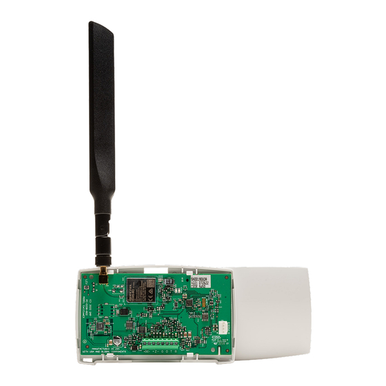
Place the antenna onto the SMA connector. Twist the antenna until it is securely tightened. Replace the housing cover on the mounted base. Be sure to not damage any PCB components when removing or replacing the housing cover. +DC- + Z - Figure 3: Antenna Connection Digital Monitoring Products CellComEX Programming and Installation Guide... -
Page 9: Applications
The panel or separate power supply must be 12 Volt Power Supply connection Regulated and Power Limited. Aux. Output Ground Normally Open Common Normally Closed 1k ohm Figure 5: Wiring Diagram for Burglary Zone CellComEX Programming and Installation Guide Digital Monitoring Products... -
Page 10: Zone Bell Connection
See Table 1 for bell cadence type, zone number, and type of message sent to the receiver. BELL CADENCE ZONE NUMBER TYPE OF MESSAGE Steady Zone 1 Burglary Pulse or Temporal 3 Zone 2 Fire Temporal 4 Zone 3 Emergency or Carbon Monoxide Table 1: Message Breakdown Digital Monitoring Products CellComEX Programming and Installation Guide... -
Page 11: Bell Capture Wiring
Note: Voltage should be read from the Z- terminal using the red probe of a multimeter. The black probe of the multimeter should be used to read voltage from the DC- terminal. CellComEX Programming and Installation Guide Digital Monitoring Products... -
Page 12: Ecp Passthru Connection
12 13 14 15 16 17 18 19 20 21 22 23 24 25 RING RING – (BROWN) (GRAY) (GREEN) (RED) From DC– From DC+ From Z- From Z+ Figure 8: ECP Passthru Wiring Digital Monitoring Products CellComEX Programming and Installation Guide... - Page 13 5.0 or higher VISTA-21iP VISTA-21iPLTE Yes Note: Panels must be programed in the Stay/Away mode for Remote Arming/Disarming (No Partitions). Vista 32, 40, 50, 128, 250 are not compatable with ECP Virtual Keypad. CellComEX Programming and Installation Guide Digital Monitoring Products...
-
Page 14: Dsc Passthru Connection
Z6 Z7 R-1 T-1 EGND RING TIP From T From R 5.6k From Z - To AC BLACK BLACK From Z + Power From DC - From DC + Figure 9: DSC Passthru Wiring Digital Monitoring Products CellComEX Programming and Installation Guide... -
Page 15: Arming And Disarming
Connect the communicator’s O (output) terminal to the control panel’s keyswitch or arming zone. Use 18-22 AWG for Power Supply connection + Z - +DC- 12 VDC Aux. Output Zone 1 Control Panel EOL resistor Zone 2 Figure 11: Communicator to Burglary Control Panel Zones CellComEX Programming and Installation Guide Digital Monitoring Products... - Page 16 Connect the communicator’s DC- terminal to terminal 4 on the control panel. LOAD RESET OUTPUT 17 +DC- + Z - Honeywell Vista 20 Series Connect to any keyswitch or arming zone. Figure 12: Vista 20 Series Control Panel to CellComEX Digital Monitoring Products CellComEX Programming and Installation Guide...
-
Page 17: Activate The Cellular Module
Find the customer and select their name. The customer’s summary page opens. In the Systems section, press the Add icon. Enter the system name. In System Type, select CellComEX. In Connection Type, select Cellular. In SIM Number, enter the SIM number and press Get Status. -
Page 18: Programming
Note: If using a graphic touchscreen keypad, It is important to plug in the keypad before powering up the CellComEX. Once the CellComEX is powered on, short the Reset Pad. Once the communicator is reset, navigate straight to Keypad to complete Programming and Diagnostics. -
Page 19: Special Keys
Select Area 2 Select Area 3 Select Area 1 Select Area 4 First Letter Third Letter Second Letter Special Character 32-Character Display Figure 13: LCD Keypad Select Keys Figure 14: Graphic Touchscreen Keypad Select Areas CellComEX Programming and Installation Guide Digital Monitoring Products... -
Page 20: Letters And Special Characters
Each programming option that displays shows the information already programmed in the communicator memory. To change the already programmed information, simply replace the information. To change a programming option that requires a YES or NO response, press the select area for the desired response. Digital Monitoring Products CellComEX Programming and Installation Guide... -
Page 21: Initialization
Choose NO to leave the remainder of the existing communicator programming intact. SURE? YES NO Choose YES to set the communicator programming back to factory default selections. Note: Choosing YES does not clear the event memory, zone, user code information. CellComEX Programming and Installation Guide Digital Monitoring Products... -
Page 22: Communication
Choose YES to enable Opening/Closing, Code Changes, and Bypass reports by user to be sent to this receiver. The default is YES. Choose NO to disable sending these reports to the receiver. Digital Monitoring Products CellComEX Programming and Installation Guide... -
Page 23: Receiver 2 Programming
Enter the second IP port number to be used with the second IP address. The IP port 2001 identifies the port used to communicate messages with the panel. The default port is 2001. CellComEX Programming and Installation Guide Digital Monitoring Products... -
Page 24: Remote Options
Selecting YES allows the communicator to send all stored messages to the receiver once communication is restored. The time at which each message was generated is also sent. Default is NO. Digital Monitoring Products CellComEX Programming and Installation Guide... -
Page 25: System Options
SCS-1R or SCS-VR receiver. The receiver must be programmed to send and receive time change updates from the host computer at least every 24 hours. Choose NO to disable automatic time change requests. The default is YES. CellComEX Programming and Installation Guide Digital Monitoring Products... -
Page 26: Hours From Gmt
Zone of the host panel Number Partition CID Identifier Checksum The new event Number 9910 3155 c 5550 18 1 110 00 010 2 DMP String CID String Figure 16: CID Format Option Digital Monitoring Products CellComEX Programming and Installation Guide... -
Page 27: Output Options
VirtualKeypad.com or Remote Link this output turns on for 0.75 seconds then turns off. This output can be used for panels that require a momentary short to an arming zone to arm and a momentary short to disarm. CellComEX Programming and Installation Guide Digital Monitoring Products... -
Page 28: Area Information
Press CMD to continue. To mark an active area as unused, delete the old name by pressing any select key then press CMD. The communicator automatically sets the name as *UNUSED*. If you have already initialized the communicator, all areas will be marked as *UNUSED*. Digital Monitoring Products CellComEX Programming and Installation Guide... -
Page 29: Zone Information
AREA NO: 1 Area Assignment All non-24-hour zones are automatically assigned to area 1. Enter the area number from 1-6 where this zone is being assigned. AREA: 1 - - - - - CellComEX Programming and Installation Guide Digital Monitoring Products... -
Page 30: Alarm Action
An output activated by a non-24-hour armed zone is turned off when the zone’s area is disarmed by a user. To enter the output number, press any select area followed by the output number 1. Digital Monitoring Products CellComEX Programming and Installation Guide... -
Page 31: Output Action
ZONE NUMBER ZONE NO: - Enter Zone 1 again to reprogram. If the zone is programmed, press the back arrow at the ZONE NO display to continue. CellComEX Programming and Installation Guide Digital Monitoring Products... -
Page 32: Stop
Lost lockout codes require the communicator to be sent back into DMP for repair. You may cancel a lockout code by entering 00000 at the set lockout code command option. Digital Monitoring Products CellComEX Programming and Installation Guide... -
Page 33: Appendix
Because the communicator duplicates the panel’s user codes, existing user codes in the Ademco/Honeywell panel, including master, must be added to the communicator. The CellComEX must also have user 2 as a master using the same user code as the host panel user 2. This is required to allow codes added via App/Browser to be sent to the host panel. -
Page 34: Diagnostics Function
This menu option displays the firmware version number of the communicator and date it was released. Exiting the Diagnostics program Press CMD until STOP displays. Press any select area. The keypad returns to the status list display. Digital Monitoring Products CellComEX Programming and Installation Guide... -
Page 35: Arming/Disarming Ademco Vista Panels
Program zone 1 as an arming zone. Zone Type displays. Choose arming zone type AR. Press CMD. Area: 1------ displays. Press CMD. Style: TOGGLE displays. Choose MNT. Go to STOP then press and select key to save and exit programming. CellComEX Programming and Installation Guide Digital Monitoring Products... - Page 36 Ademco Vista 20P to CellComEX for Remote Arming/Disarming +DC- + Z - 1 2 3 4 5 6 7 8 (USE SA4120XM-1 CABLE) SYNC BLACK DATA Ademco Vista 20P VISTA 20P ONLY RING RING (BROWN) (GRAY) (GREEN) (RED) Figure 17: Ademco Vista 20P to CellComEX...
-
Page 37: Fcc Notice
L’exploitation est autorisée aux deux conditions suivantes : (1) l’appareil ne doit pas produire de brouillage, et (2) l’utilisateur de l’appareil doit accepter tout brouillage radioélectrique subi, même si le brouillage est susceptible d’en compromettre le fonctionnement. Warning: Owner’s instruction notice, not to be removed by anyone except occupant. CellComEX Programming and Installation Guide Digital Monitoring Products... - Page 38 Specifications Certifications CellComEX Cellular Primary Power Nominal 12 VDC FCC Part 15: XMR201907BG95M3 Current Draw 12 VDC IC: 10224A-2019BG95M3 Standby 88 mA Underwriters Laboratories (UL) Listed Alarm 137.5 mA (Cell Communication) ANSI/UL 1610 Central Station Burglar Dimensions ANSI/UL 1023 Household Burglar ANSI/UL 985 Household Fire Warning (CID Capture) Dimensions 4.5 W x 2.75 H x 1.75 D in...
Need help?
Do you have a question about the CellComEX and is the answer not in the manual?
Questions and answers