Chapters
Table of Contents

Related Manuals for Wöhner OMUS 30Compact


Summary of Contents for Wöhner OMUS 30Compact
- Page 1 OMUS® Bedienungsanleitung ® OMUS Electronic hybrid switch for resistive loads. Bedienungsanleitung / User manual Revision 8, März 2017 Revision 8, März 2017 94 799 000 A Seite 0 von 71...
- Page 2 OMUS® Bedienungsanleitung Seite 1 von 71 94 799 000 A Revision 8, März 2017...
-
Page 3: Table Of Contents
OMUS® Bedienungsanleitung Inhalt Ausführungsvarianten .............................. 3 ® OMUS Überblick ..............................4 Applikation ................................5 ® Einbindung des OMUS in die Anlagensteuerung ....................6 Galvanische Trennung & Kurzschlussschutz ......................6 Leitungsschutz ................................ 8 Schaltvorgänge in der Hybridstufe .......................... 8 Einhalten der Grenzwerte bei Schaltvorgängen ..................... 8 Regelbarkeit der Ausgangsleistung ........................ -
Page 4: Ausführungsvarianten
OMUS® Bedienungsanleitung 1 Ausführungsvarianten OMUS®30Compact Ausführung Gewicht Art.-Nr. kg/100 OMUS®30Compact, IEC 45,2 36 152 OMUS®30Compact, UL und IEC 45,2 36 157 OMUS®60Classic Ausführung Gewicht Art.-Nr. kg/100 OMUS®60Classic, IEC 45,8 36 153 OMUS®60Classic, UL und IEC 45,8 36 158 OMUS®CrossBoard Ausführung Gewicht Art.-Nr. -
Page 5: Omus Überblick
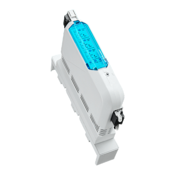
OMUS® Bedienungsanleitung ® 2 OMUS Überblick OMUS® Elektronischer Hybridschalter für ohmsche Lasten. Sammelschienenadapter (*Ausführung 30Compact) Laststecker Klappdeckel Plombierung Esc / Reset-Taster Steuerstecker ® Der elektronische Hybridschalter OMUS ist ein kompaktes Schaltgerät mit 36mm Baubreite. Hybridschalter besteht einer Kombination Relaiskontakten Leistungshalbleitern, integriertem Kurzschlussschutz sowie elektronischer Strom- und Temperaturüberwachung zum betriebsmäßigen Schalten von ohmschen Verbrauchern (IEC bis 25A / 400V AC;... -
Page 6: Applikation
OMUS® Bedienungsanleitung 2.1 Applikation ® Der Hybridschalter OMUS wurde für Einsatzbereiche entwickelt, in denen bisher Schütze, Überlastrelais, Solid State Relais und mechanische Schalter eingesetzt wurden. Das Gerät wurde konzipiert für das häufige Schalten von: • 1-poligen ohmschen Lasten (Phase-Neutralleiter) sowie •... -
Page 7: Einbindung Des Omus In Die Anlagensteuerung
OMUS® Bedienungsanleitung ® 2.2 Einbindung des OMUS in die Anlagensteuerung ® Die Ansteuerung des OMUS kann z.B. mit Hilfe einer Speicher-programmierbaren Steuerung ® (SPS) erfolgen. Die genaue Spezifikation der Eingangssignale des OMUS ist in Kapitel 9 Technische Daten sowie 2.5 Schaltvorgänge in der Hybridstufe detailliert beschrieben. Die definierten Grenzwerte wie z.B. - Page 8 OMUS® Bedienungsanleitung ® Zum anderen kann die galvanische Trennung zwischen OMUS und entsprechender Last erfolgen. Galvanische Trennung seitens der Last: Typische Vertreter für die Umsetzung der galvanischen Trennung sind Schütze oder ® Leistungsschalter. Im nicht betriebsgemäßen Zustand gibt das Störungsrelais des OMUS Meldung.
-
Page 9: Leitungsschutz
OMUS® Bedienungsanleitung 2.4 Leitungsschutz Der Leitungsschutz der angeschlossenen Leitung erfolgt über das eingestellte Stromlimit (16A, ® 20A oder 25A). Um den Leitungsschutz des OMUS beim eingestellten Strom zu gewährleisten, müssen mindestens folgende Leitungsquerschnitte Laststecker ® eingehalten werden. Die aufgeführten Werte entsprechen der OMUS Einzelaufstellung. - Page 10 OMUS® Bedienungsanleitung Grenzparameter kann die korrekte Funktionalität des Gerätes nicht gewährleistet werden. Die Elektronik überwacht ständig die ordnungsgemäße Ausführung der Steuerbefehle und die Stromaufnahme in allen Phasen. Um hohe Schalthäufigkeit, lange Lebensdauer und geringe Verlustleistung zu erreichen, müssen Schaltvorgänge nach folgenden Regeln erfolgen: •...
- Page 11 OMUS® Bedienungsanleitung Beispielhafter Ein- und Ausschaltvorgang mit Hybridstufen im Detail (Stromfluss) Laststrom Relais Laststrom Halbleiter Schaltsignal Triac ON Triac ON Relais ON Zeit t in ms Bezeichnung Grenzwert Im Beispiel (Einschaltdauer der Triac) max. 20ms ca. 8ms Einschalten Triac ON ca.
-
Page 12: Regelbarkeit Der Ausgangsleistung
OMUS® Bedienungsanleitung 2.7 Regelbarkeit der Ausgangsleistung ® Die Regelbarkeit der Ausgangsleistung des OMUS geschieht in Abhängigkeit der Ansteuerung. Im Dauerbetrieb wird der Verbraucher durchgehend angesteuert. Um die Ausgangsleistung zu verringern kann der Ausgang getaktet geschaltet werden. Der sogenannte Aussteuergrad D (duty cycle) beschreibt das Verhältnis von der Dauer des Ansteuerimpulses zur Periodendauer der Taktung: ��... -
Page 13: Eignung Der Anwendung
OMUS® Bedienungsanleitung 2.8 Eignung der Anwendung ® Grundlage für den Einsatz des OMUS in der geplanten Applikation ist der Betrieb innerhalb der folgenden Grenzparameter. ® Elektrische Parameter OMUS Vorgabe Art des Verbrauchers ohmsche Lasten Max. Laststromstärke I 25A (IEC) 20A (UL) nc max Min. -
Page 14: Sicherheitsbestimmungen / Errichtungshinweise
OMUS® Bedienungsanleitung 3 Sicherheitsbestimmungen / Errichtungshinweise Beachten Sie bei allen Arbeiten am Gerät die nationalen Sicherheits-, Unfallverhütungs- und Arbeitsschutzvorschriften. Werden die Sicherheitsvorschriften nicht beachtet, können hohe Sachschäden, schwere Gesundheitsschäden oder sogar Gefahr für Leib und Leben die Folge sein. Inbetriebnahme, Montage, Änderung und Nachrüstung dürfen nur von einer Elektrofachkraft ausgeführt werden! Schalten Sie das (Sammelschienen-)System vor Beginn der Arbeiten am Gerät oder den Lasten spannungsfrei! Bei Durchlegieren der Halbleiterelemente oder bei Verkleben der Relais... -
Page 15: Produkttabelle
OMUS® Bedienungsanleitung 4 Produkttabelle Gewicht kg/100 Art.-Nr. OMUS®30Compact Elektronischer Hybridschalter IEC, 3-polig, komplett mit Sammelschienenadapter, Steuer- und Laststecker sowie 45,2 36 152 Sicherungseinsätzen 32A gG, 10 × 38 Elektronischer Hybridschalter UL und IEC,3-polig, komplett mit Sammelschienenadapter, Steuer- und Laststecker sowie 45,2 36 157 Sicherungseinsätzen Class CC 30A time delay... -
Page 16: Inbetriebnahme
OMUS® Bedienungsanleitung 5 Inbetriebnahme Sicherheitshinweise und Verwendungsbereich sind zu beachten. 5.1 Anschlüsse Klemmenbelegung Steuerleitung Anschluss Bezeichnung Funktion +24V DC +24 V DC Bemessungssteuerspeisespannung Funktionserde E L2 Steuereingang für L2 E (L1 + L2 + L3) Steuereingang für L1 + L2 + L3 Warnung Meldeausgang für Warnung (95) Störung... -
Page 17: Montage Und Anschluss
OMUS® Bedienungsanleitung 5.2 Montage und Anschluss Montage auf das Sammelschienensystem: Das komplette Modul einschließlich Sammelschienen- adapter auf die Schienen aufrasten. Die elektrische Verbindung zum 3-Phasen-Netz erfolgt direkt über den Adapter. Falls erforderlich, vor dem Aufrasten die Rastfüße des Sammelschienenadapters auf 10mm Sammelschienen anpassen. -
Page 18: Bedeutung Der Led Anzeigen
OMUS® Bedienungsanleitung 5.3 Bedeutung der LED Anzeigen • Autobetrieb: LEDs Dauerlicht grün (vgl. Kapitel 6.2 Übersicht Anzeigefunktionen) • Warnung: LEDs orange • ® Störung: LEDs rot + Abschaltung des OMUS 5.4 Demontage, Austausch von Geräten Freischalten des Sammelschienensystems, Sicherheitshinweise beachten! Entfernen des Steuersteckers: Entfernen des Laststeckers: ®... -
Page 19: Austausch Einer Sicherung
OMUS® Bedienungsanleitung 5.5 Austausch einer Sicherung Freischalten des Sammelschienensystems, Sicherheitshinweise beachten! ® OMUS vom Adapter abnehmen: Sicherungsdeckel öffnen: Sicherung tauschen: Sicherungstausch nur bei demontiertem Gerät! ® ® ® OMUS auf den Adapter aufrasten: OMUS auf das Crossboard aufrasten: Auf die korrekte Position des Rastschiebers (vgl. Montageschritt 5) sowie den Verpolschutz ist zu achten! Revision 8, März 2017 94 799 000 A... -
Page 20: Checkliste
OMUS® Bedienungsanleitung 5.6 Checkliste Am Ende der Inbetriebnahme folgende Checkliste abarbeiten und zutreffendes ankreuzen, um den sicheren Betrieb des Gerätes zu gewährleisten. Parameter Beschreibung Status Sicherung Sicherungen eingelegt und funktionstüchtig Einspeiseschnittstelle Korrekte Verrastung auf dem System Laststecker Korrekte Verrastung und Verkabelung des Laststeckers ... -
Page 21: Bedienerschnittstellen
OMUS® Bedienungsanleitung 6 Bedienerschnittstellen 6.1 Frontansicht • Autobetrieb: LEDs Dauerlicht grün (vgl. Kapitel 6.2 Übersicht Anzeigefunktionen) • Warnung: LEDs orange • ® Störung: LEDs rot + Abschaltung des OMUS Hand ON Taster L1 Haupt LED L1 Hand LED L1 Auto(matik) LED L1 Stromlimits 16A, 20A, 25A Enter Taster Select Taster... -
Page 22: Übersicht Anzeigefunktionen
OMUS® Bedienungsanleitung 6.2 Übersicht Anzeigefunktionen Die detaillierte Beschreibung der verschiedenen Betriebszustände ist Kapitel 8 zu entnehmen. Auto(matik)betrieb (Haupt-LED: grün) Status Haupt-LED Auto-LED Hand-LED Stromlimits Warnung Störung Last Werkseinstellung grün grün grün (16A) geschaltet Auto(matik)betrieb 16A grün grün grün (16A) geschaltet Auto(matik)betrieb 20A grün grün... -
Page 23: Eplan-Symbol
OMUS® Bedienungsanleitung 6.3 Eplan-Symbol Revision 8, März 2017 94 799 000 A Seite 22 von 71... -
Page 24: Schaltungsvarianten
OMUS® Bedienungsanleitung 6.4 Schaltungsvarianten Anwendungen Last Bei Anwendungen ohne Bei 2-pol. Anw. ohne Der Betrieb in gegen Neutralleiter Neutralleiter darf nur Neutralleiter darf einpoligen können beliebig allpolig L1+L2+L3 nur allpolig L1+L2+L3 Netzen ist (einzeln oder (Anschluss 4 (Anschluss 4 unzulässig! zusammen) Steuerstecker) geschaltet Steuerstecker) -
Page 25: Konfiguration Des Omus
OMUS® Bedienungsanleitung ® 7 Konfiguration des OMUS ® Das Einstellungsmenü ermöglicht dem Anwender den OMUS entsprechend der Applikation zu konfigurieren. Die Einstellung der Stromlimits in den Stufen 16A, 20A und 25A ist vom Anwender gemäß den Anforderungen und Grenzen der Anlage vorzunehmen. Als Betriebsmodi stehen zum einen der Auto(matik)betrieb zur Verfügung, der über 24V DC Eingänge gesteuert wird (z.B. -
Page 26: Menüstruktur
OMUS® Bedienungsanleitung 7.1 Menüstruktur Anhand der nachfolgenden Abbildung wird die Menüstruktur graphisch beschrieben. Die anschließenden Seiten beschreiben die Einstellungen für eine oder alle drei Phasen. Hauptanzeige Select 30s / Reset Stromlimit einstellen 3-phasig Select 30s / Reset Betriebsart einstellen 3-phasig Select 30s / Reset Stromlimit L1... -
Page 27: Dreiphasige Einstellungen
OMUS® Bedienungsanleitung 7.2 Dreiphasige Einstellungen Die dreiphasige Einstellung des Stromlimits ist nachfolgend abgebildet: Hauptanzeige Change Select Change Change Change Stromlimit einstellen 3-phasig Enter Enter Enter Select Betriebsart einstellen 3-phasig Stromlimit 3-phasig gespeichert Die dreiphasige Einstellung der Betriebsart ist nachfolgend abgebildet: Stromlimit einstellen 3-phasig Change Select... -
Page 28: Einphasige Einstellungen
OMUS® Bedienungsanleitung 7.3 Einphasige Einstellungen Die einphasige Einstellung eines Stromlimits ist nachfolgend abgebildet: Betriebsart einstellen 3-phasig Change Select Change Change Change Stromlimit einstellen L1 Enter Enter Enter Select Betriebsart einstellen L1 Stromlimit L1 gespeichert Die einphasige Einstellung eines Betriebsmodus ist nachfolgend abgebildet: Stromlimit einstellen L1 Change Select... -
Page 29: Wiederherstellung Des Werkszustands
OMUS® Bedienungsanleitung 7.4 Wiederherstellung des Werkszustands Bei Auslieferung sind alle Phasen auf Auto(matik)betrieb und die Stromlimits auf 16A ® eingestellt. Um den OMUS in den Auslieferungszustand zurückzusetzen, sind die Select- und Enter-Taste gleichzeitig zu drücken. Alle LEDs leuchten beim gleichzeitigen Tastendruck auf und zeigen durch mehrmaliges Blinken die erfolgreiche Wiederherstellung des Auslieferungszustands an. -
Page 30: Funktionsbeschreibung
OMUS® Bedienungsanleitung 8 Funktionsbeschreibung Das Gerät verfügt über verschiedene Betriebszustände: • Auto(matik)betrieb • Handbetrieb • Einstellungsmenü • Warnungs- und Störungszustände • Standby-Modus Warnungen werden bei laufendem Betrieb ausgegeben. Störungen schalten die Last ab. Durch gleichzeitiges Drücken der „Select-Taste“ + „Enter-Taste“ kann der Hybridschalter auf den ursprünglichen Auslieferzustand zurückgesetzt werden. -
Page 31: Warnung
OMUS® Bedienungsanleitung 8.4 Warnung Folgende Zustände führen zu Warnmeldungen: • Phasenausfall / Sicherung ausgelöst • Ausfall Last • Geringer Überstrom - Stromlimit erreicht • Geringe Übertemperatur - Temperaturwarnung ab 65°C Einbindung von Warnungen in die SPS und Vermeidung von Fehlalarmen: Warnungen sollten erst nach 500ms Dauermeldung ausgewertet werden. -
Page 32: Störung
OMUS® Bedienungsanleitung Geringer Überstrom Erreicht der gemessene Laststrom das eingestellte Stromlimit wird dies als Warnung ausgegeben. Die Haupt-LED der betroffenen Phase blinkt orange und die eingestellte Stromlimit-LED blinkt grün. Das Warnungsrelais gibt Meldung. Nach Beseitigung der Ursache für den Überstrom quittiert sich die Warnung selbst. Der laufende Betrieb wird nicht unterbrochen. -
Page 33: Quittieren Von Meldungen
OMUS® Bedienungsanleitung Starker Überstrom Übersteigt der gemessene Laststrom das eingestellte Stromlimit um mehr als 15%, wird die betroffene Last abgeschaltet. In der betroffenen Phase wird die Haupt-LED rot und die eingestellte Stromlimit-LED blinkt grün. Das Störungsrelais gibt dauerhaft Meldung. Nach Beseitigung der Ursache für den Überstrom, ist die Quittierung der Störmeldung notwendig (Esc/Reset-Taster) um den Betrieb wieder aufzunehmen. -
Page 34: Technische Daten
OMUS® Bedienungsanleitung 9 Technische Daten Umgebungsbedingungen Umgebungstemperatur -5°C bis 35°C im Schaltschrank bei Temperaturen bis 55°C bzw. Verbundanordnung siehe Derating Verschmutzungsgrad 2, im Gehäuse Überspannungskategorie II, Lastebene Hauptstromkreise Schaltungsprinzip 3 getrennte Schaltstufen mit Bypass L1, L2, L3 Anzahl der Hauptstromkreise 3 unabhängige Stromkreise L1, L2 und L3 für ohmsche Lasten Bemessungsbetriebsspannung U... - Page 35 OMUS® Bedienungsanleitung Zeiten Max. Schaltfrequenz Min. Dauer des Ansteuerimpulses 100ms Min. Einschaltdauer der Last 100ms Min. Ausschaltdauer der Last 100ms Max. Einschaltverzögerung 80ms Max. Ausschaltverzögerung 80ms Steuerstromkreise Bemessungssteuerspeisespannung U nach IEC 60947-1 24V DC UL 508 26,5V DC Steuerspeisespannung, Schaltpegel „Sicher aus“ <...
- Page 36 OMUS® Bedienungsanleitung Derating bezogen auf 25A Dauerstrom auf Sammelschienensystem nach IEC 61439-2 Aufstellung in Umgebung bis 35°C 45°C 55°C Einzelaufstellung / Abstand ≥ 36mm RDF = 1,0 RDF = 0,9 RDF = 0,8 Anordnung mit Abstand ≥ 9mm RDF = 0,9 RDF = 0,8 RDF = 0,7 Verbundanordnung, Abstand 0mm (4 Geräte)
- Page 37 OMUS® user manual ® OMUS Electronic hybrid switch for resistive loads. User manual Revision 8, March 2017 Revision 8, March 2017 94 799 000 A Page 36 of 71...
- Page 38 OMUS® user manual Contents Design variants ............................... 38 ® OMUS Overview ..............................39 Application ................................40 ® Incorporation of OMUS into process control ....................... 41 Galvanic isolation & short-circuit protection ......................41 Line protection ..............................43 Switching processes in the hybrid switch ......................43 Adhering to limit values in switching processes ....................
-
Page 39: Design Variants
OMUS® user manual 1 Design variants OMUS®30Compact Type Pack Size Weight Part No. kg/100 OMUS®30Compact, IEC 45.2 36 152 OMUS®30Compact, UL and IEC 45.2 36 157 OMUS®60Classic Type Pack Size Weight Part No. kg/100 OMUS®60Classic, IEC 45.8 36 153 OMUS®60Classic, UL and IEC 45.8 36 158 OMUS®CrossBoard... -
Page 40: Omus Overview
OMUS® user manual ® 2 OMUS Overview OMUS® Electronic hybrid switch for resistive loads. Busbar adapter (*version 30Compact) Load plug Hinged cover Lead sealing Esc / Reset button Control plug ® The OMUS electronic hybrid switch is a compact switching device with a width of 36 mm. The hybrid switch is composed of a combination of relay contacts and power semi-conductors, integrated short-circuit protection as well as electronic current and temperature monitoring for operational switching of resistive loads (IEC up to 25 A / 400V AC;... -
Page 41: Application
OMUS® user manual 2.1 Application ® The OMUS hybrid switch has been developed for areas of application in which contactors, overload relays, solid state relays and mechanical switches have previously been used. This device was designed for the frequent switching of: •... -
Page 42: Incorporation Of Omus ® Into Process Control
OMUS® user manual ® 2.2 Incorporation of OMUS into process control ® OMUS can be actuated with the help of a programmable logic controller (PLC). The precise ® specification for the input signals of OMUS is described in detail, in chapter 9 Technical data, as well as in 2.5 Switching processes in the hybrid switch. - Page 43 OMUS® user manual ® The galvanic isolation can also be realized between OMUS and corresponding load. Galvanic isolation on the part of the load: load Common devices for the implementation of a galvanic isolation are contactors or circuit ® breakers. In a non-operational status, the OMUS error relay will issue a signal.
-
Page 44: Line Protection
OMUS® user manual 2.4 Line protection The line protection of the connected line is realized by setting the correct current limit (16A, ® 20A or 25A). In order to ensure line protection with OMUS depending on the configured current, at least the following wire cross-sections at the load plug have to be adhered to. The ®... - Page 45 OMUS® user manual performance of the control commands and the power consumption in all phases. Switching processes must be conducted in line with the following rules in order to achieve a high switch rate, long lifetime and low power loss: •...
- Page 46 OMUS® user manual Exemplary switch on and off process with hybrid switches in detail (current flow) Triac ON Triac ON Relay ON Designation Limit value In example (Switch on duration of Triac) max. 20ms approx. 8ms switch on Triac ON approx.
-
Page 47: Adjustability Of The Power Output
OMUS® user manual 2.7 Adjustability of the power output ® The adjustability of the power output of OMUS occurs depending on the actuation. In continuous operation, the consumer is continuously actuated. The output can be switched in a timed manner to reduce the power output. The duty cycle D is characterized by the relationship between duration of the actuation impulse and period duration of the timing: ��... -
Page 48: Suitability Of The Application
OMUS® user manual 2.8 Suitability of the application ® The basis for the use of OMUS in the planned application is operation within the following limit parameters. ® Electrical parameters OMUS Specification Type of load resistive loads Max. load current I 25A (IEC) 20A (UL) nc max... -
Page 49: Safety Instructions / Installation Instructions
OMUS® user manual 3 Safety instructions / Installation instructions Obey all national safety, accident prevention and industrial safety regulations when carrying out work on the device. Failure to obey safety instructions may result in a good deal of property damage, severe health damage or even danger to life and limb. The device may only be commissioned, installed, modified and retrofitted by a trained electrician. -
Page 50: Product Table
OMUS® user manual 4 Product table Type Pack Weight kg/100 Part No. Size OMUS®30Compact Electronic hybrid switch IEC, 3-pole, complete with busbar adapter, 45.2 36 152 control and load plug and fuse links 32A gG, 10 x 38 Electronic hybrid switch UL and IEC, 3-pole, complete with busbar adapter, control and load plug and fuse links Class CC 30A time 45.2 36 157... -
Page 51: Commissioning
OMUS® user manual 5 Commissioning Refer to the safety instructions and area of use. 5.1 Connections Terminal assignment control cable Connection Designation Function +24V DC +24 V DC design control supply voltage Functional ground E L2 Control input for L2 E (L1 + L2 + L3) Control input for L1 + L2 + L3 Warning... -
Page 52: Installing And Connecting The Main Circuits
OMUS® user manual 5.2 Installing and connecting the main circuits Mounting on the busbar system: Lock the complete module including the busbar adapter to the rails. The electrical connection to the three-phase conductors is made through the adapter. If necessary, adjust the busbar adapter's feet for 10mm busbars beforehand. -
Page 53: Meaning Of The Led Indicators
OMUS® user manual 5.3 Meaning of the LED indicators • Auto(matic) mode: LEDs permanently green (compare chapter 6.2 Overview of display functions) • Warning: LEDs orange • ® Error: LEDs red + OMUS switched off 5.4 Disassembly and replacing devices Disconnect power to the busbar system, obey safety instructions! Remove the control plug: Remove the load plug... -
Page 54: Replacing A Fuse
OMUS® user manual 5.5 Replacing a fuse Disconnect power to the busbar system, obey safety instructions! Remove the OMUS® from the adapter: Open fuse cover: Exchange fuse: Do not exchange the fuse before dismantling! ® ® ® Snap the OMUS onto the adapter: Snap the OMUS onto the CrossBoard... -
Page 55: Checklist
OMUS® user manual 5.6 Checklist Work through the following checklist at the end of commissioning and check all corresponding points to guarantee the safe operation of the device. Parameter Description Status Fuse Fuses in place and functional Busbar adapter Correct locking with the system ... -
Page 56: User Interface
OMUS® user manual 6 User interface 6.1 Front view • Normal operation: LEDs permanently green (compare chapter 6.2 Overview of display functions) • Warning: LEDs orange • ® Error: LEDs red + OMUS switched off Hand ON button L1 Main LED L1 Manual LED Auto(matic) LED L1 Current limits 16A, 20A, 25A... -
Page 57: Overview Of Display Functions
OMUS® user manual 6.2 Overview of display functions The detailed description of the different operation modes is shown in chapter 8. Auto(matic) mode (main LED: green) Status Main LED Auto LED Manual Current limits Warning Error Load Factory setting Green Green Green (16A) Switched... -
Page 58: Eplan Symbol
OMUS® user manual 6.3 Eplan symbol Page 57 of 71 94 799 000 A Revision 8, March 2017... -
Page 59: Switching Variants
OMUS® user manual 6.4 Switching variants Usage of load For applications For 2-pole usage without Not suitable for against neutral without a neutral neutral conductor, the operating in conductor offers conductor, the usage usage of the 3-phase single-phase switching as of the 3-phase input input L1+L2+L3 (input 4 networks... -
Page 60: Configuration Of Omus
OMUS® user manual ® 7 Configuration of OMUS ® The settings menu allows the user to configure OMUS in line with the application. The setting of the current limits at the levels 16A, 20A and 25A must be done by the user in accordance with the requirements and limits of the installation. -
Page 61: Menu Structure
OMUS® user manual 7.1 Menu structure The menu structure is visualized in the following diagram. The following pages visually describe the settings for single phase or all three phases. Main display Select 30s / Reset Set 3-phase current limit Select 30s / Reset Set 3-phase operating mode Select... -
Page 62: Three-Phase Settings
OMUS® user manual 7.2 Three-phase settings The three-phase setting of the current limits is pictured as follows: Main display Change Select Change Change Change Set 3-phase current limit Enter Enter Enter Select Set 3-phase operating mode Current limit saved in 3-phase The three-phase setting of the operating mode is pictured as follows: Set 3-phase current limit Change... -
Page 63: Single-Phase Settings
OMUS® user manual 7.3 Single-phase settings The single-phase setting of a current limit is pictured as follows: Set 3-phase operating mode Change Select Change Change Change Set current limit L1 Enter Enter Enter Select Set operating mode L1 Current limit L1 saved The single-phase setting of an operating mode is pictured as follows: Set current limit L1 Change... -
Page 64: Restoring To Factory Settings
OMUS® user manual 7.4 Restoring to factory settings On delivery all phases are set to auto(matic) mode and the current limits to 16A. If you want ® OMUS to be reset to the delivery status, press Select and Enter button simultaneously. This simultaneous pressing of the buttons will cause all LEDs to be illuminated and display the successful restoration of the delivery status by flashing multiple times. -
Page 65: Function Description
OMUS® user manual 8 Function description The device has various operating states: • auto(matic) mode • manual mode • settings menu • warning and error states • standby mode Warnings are issued during running operation. Errors turn the load off. The factory settings can be restored by pressing the "select"... -
Page 66: Warning
OMUS® user manual 8.4 Warning The following statuses will lead to a warning: • Phase failure / Blown fuse • Load failure • Minor overcurrent - current limit reached • Minor overtemperature - temperature warning above 65 °C PLC integration of warnings and avoidance of false alarms: Warnings below 500ms should not be evaluated. -
Page 67: Error
OMUS® user manual Minor overcurrent If the measured load current reaches the set current limit, this is detected as a warning. The main LED for the affected phase will flash orange and the set current limit LED will flash green. The warning relay will issue a signal. -
Page 68: Acknowledgement Of Messages
OMUS® user manual Major Overcurrent If the measured load current exceeds the set current limit by more than 15%, the affected load is shut down. In the affected phase, the main LED turns red and the set current limit LED will flash green. -
Page 69: Technical Data
OMUS® user manual 9 Technical data Ambient conditions Ambient temperature -5°C to 35°C in control cabinet; for temperatures up to 55°C or group layout see derating Pollution degree 2, in the housing Overvoltage category II, Load level Main circuits Switching principle 3 separate switches with bypass L1, L2, L3 Number of main circuits 3 independent circuits L1, L2 and L3 for resistive... - Page 70 OMUS® user manual Timing Max. switching frequency Min. duration of actuation ports 100 ms Min. switch on duration of load 100 ms Min. switch off duration of load 100 ms Max. switch on delay 80ms Max. switch off delay 80ms Control circuits Design control supply voltage U IEC 60947-1...
- Page 71 OMUS® user manual Derating relative to 25A continuous current through busbar system according to IEC 61439-2 Installation ambient temperature up to 35°C 45°C 55°C Single installation/Gap ≥ 36mm RDF = 1.0 RDF = 0.9 RDF = 0.8 Layout with gap ≥ 9mm RDF = 0.9 RDF = 0.8 RDF = 0.7...
- Page 72 OMUS® user manual Page 71 of 71 94 799 000 A Revision 8, March 2017...
Need help?
Do you have a question about the OMUS 30Compact and is the answer not in the manual?
Questions and answers