Advertisement
Advertisement
Table of Contents

Related Manuals for KPS KPS-MT720


Summary of Contents for KPS KPS-MT720
- Page 1 KPS-MT720 CAT I V CAT III...
- Page 2 This instrument meets EN 61010-1, EN 61010-2-030, EN 61010-2-033 standards for safety requirements for electronic testing instruments, pollution degree 2 and over voltage rating of CAT III 1000V and CAT IV 600V. Follow all safety instruments to ensure use of the instrument. Proper use and protection of the meter will ensure long lift of the meter.
- Page 3 1.3 Symbols Note-Important safety information, refer to the instruction manual. Caution, possibility of electric shock Equipment protected throughout by double insulation or reinforced insulation. Conforms to UL STD. 61010-1, 61010-2-032, 61010-2-033; Certified to CSA STD C22.2 NO. 61010-1, 61010-2-032,61010-2-033 Complies with European (EU) safety standards Earth (ground) TERMINAL Both direct and alternating current CAT III: MEASUREMENT CATEGORY III is applicable to...
-
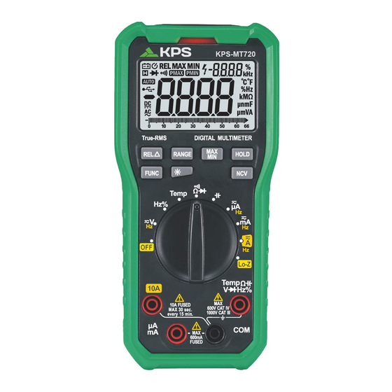
Page 4: Lcd Display
2.2 Buttons and Symbols HOLDbutton: hold current reading on screen. FUNC button: switch between functions. RANGE button: switch between auto/manual ranges. REL button: relative reading MAX/MIN button: switch between maximum/ minimum readings. -:+:- button: turn on/off backlight. EMP position: thermocouple temperature measurement. LO-Z position: identify ghost voltages. -
Page 5: General Specifications
3. Specifications Alternating current The Meter should be calibrated annually between Direct current ° ° C~28 C and a relative humidity less than 75%. Diode 3.1 General Specifications Continuity 01)) 3.1.1 Manual and auto range Autoranging mode AUTO 3.1.2 Full range overload protection Maximum value 3.1.3The maximum voltage allowed between the measuring Minimum value... -
Page 6: Technical Specifications
3.2.3 DC Voltage 3.2 Technical Specifications range 3.2.1 True RMS Characteristics Resolution Accuracy ±(0.8% of reading+ 3 digits) • For non-sinusoidal signal measurement, the Meter 660mV 0.1mV provides more accurate measurement than the 6.6V 0.001V traditional averaging method. 0.01V • If in AC current mode, the Meter may display a random ±(0.5% of reading+ 5 digits) 660V 0.1V... - Page 7 10pF...
- Page 8 3.2.9 Frequency 3.2.10 DC Current 3.2.9.1 Frequency (V position): range Resolution Accuracy range Resolution Accuracy 660µA 0.1µA 66Hz 0.01Hz 6600µA 1µA ±(1.0% reading+ 5 digits) 660Hz 0.1Hz 10µA 66mA ±(1.5% reading+ 5 digits) 6.6kHz 0.001kHz 100µA 660mA 10kHz 0.01kHz ±(2.0% reading+ 5 digits) 10mA - Range: 1 0Hz-10kHz Overload protection:...
-
Page 9: Using The Meter
3.2.12 Temperature 4 .3.2 Press "RELL'.::." again to return to normal. 4.4 Maximum/Minimum Reading Range Input Test Range Accuracy 4. 4 . 1 Press "MAX/MIN" to display the maximum value Ambient Temp 2 digits ± recorded ° ° 4 digits 0 ~1000 C 4 00 ±... - Page 10 Note, 4.11 Continuity 1.Even though there is no indication.voltage may still 4.11.1 In resistance mode, press "FUNC" to switch to exist.Do not rely solely on NCV detector to determine continuity mode. the presence of voltage in a wire.The measurement 4.11.2 Connect the red test lead to the input jack and the may be affected by the design of the outlet.type of black test lead to the "COM"...
- Page 11 5.2 Replacing Test Leads Replace test leads if leads become damaged or worn. WARNING Use meet EN 61010-031 standard, rated CA T III 1000V, or better test leads. 1pcs 1pcs 1pcs 1pcs 1pcs...
Need help?
Do you have a question about the KPS-MT720 and is the answer not in the manual?
Questions and answers