Table of Contents
Advertisement
Quick Links
Advertisement
Table of Contents

Related Manuals for Wolf Steel WSC-IS

Summary of Contents for Wolf Steel WSC-IS
- Page 1 INSTALLATION & USER GUIDE WSC43BA Thermostat Wolf Steel Ltd., 24 Napoleon Rd., Barrie, ON, L4M 0G8 Canada / 103 Miller Drive, Crittenden, Kentucky, USA, 41030 Phone 1 (866) 820-8686 • www.napoleon.com • hvac@napoleon.com W415-4094 / C-0 / 03.19.24...
- Page 2 Model Product Name FCC ID IC ID Number Touchscreen 7114A- WSC43BA VA8-WSC43BA Thermostat WSC43BA Indoor PIR Temperature WSC-IS Sensor 7114A- VA8-WSC-IS WSCIS Outdoor Temperature WSC-OS Sensor with Probe Thermostat Power WSC- Module PWRM (not included) This device complies with Part 15 of the FCC Rules. Operation is subject to the following two conditions: 1) The device may not cause harmful interference;...
- Page 3 SAFETY HANDLING Changes or modifications not expressly approved by the party responsible for compliance could void the user’s authority to operate the equipment. NOTE: This equipment has been tested and found to comply with the limits for a Class B digital device, pursuant to Part 15 of the FCC Rules.
-
Page 4: Table Of Contents
The information throughout this manual is believed to be correct at the time of NOTE: printing. Wolf Steel Ltd. reserves the right to change or modify any information within this manual at any time without notice. Changes, other than editorial, are denoted by a vertical line in the margin. -
Page 5: Welcome
IN THE BOX Indoor Sensor Installation & WSC43BA Thermostat Outdoor Sensor (WSC-IS) User Guide Label 1. Y/Y1 Y/Y1 Label 1. RH Y2 If you have a C... -
Page 6: Wiring Diagrams
WIRING DIAGRAMS Below are the wiring diagrams for common HVAC equipment. Conventional Heating and Cooling System Humidifier/Dehumidifier Y2 W1 W2 (optional) Furnace/Air Handler Air conditioner Optional Remove the jumper between Rh, Rc, or R terminals. Adjust the DIP switch on the back of the thermostat to “Disconnect” if you have connected both RC-wire and RH-wire to the wall-plate. - Page 7 WIRING DIAGRAMS Heat Pump with Furnace Humidifier/ Dehumidifier (optional) W1 W2 O/B D Y1 Y2 Furnace Heat pump Optional Remove the jumper between Rh, Rc, or R terminals. Adjust the DIP switch on the back of the thermostat to “Disconnect” if you have connected both RC-wire and RH-wire to the wall-plate.
- Page 8 WIRING DIAGRAMS Heat Pump with Air Handler Humidifier/ Dehumidifier (optional) W1/D W2 Y1 Y2 Air Handler Heat pump Optional Remove the jumper between Rh, Rc, or R terminals. Adjust the DIP switch on the back of the thermostat to “Disconnect” if you have connected both RC-wire and RH-wire to the wall-plate.
- Page 9 WIRING DIAGRAMS Boiler or Radiant System with Air Handler and Conventional Cooling or Heat Pump Air handler Humidifier/ Dehumidifier Air conditioner or Heat pump Boiler (optional) Optional For heat pump only. Remove the jumper between Rh, Rc, or R terminals. Adjust the DIP switch on the back of the thermostat to “Disconnect”...
-
Page 10: Installation Guide
INSTALLATION GUIDE REMOVING YOUR OLD THERMOSTAT Step 1: Switch off your HVAC system Before you start, please switch off your HVAC system to protect you and to avoid blowing a fuse. Wait a few minutes, then try to adjust the temperature of your old thermostat to verify that the system is off. - Page 11 INSTALLATION GUIDE Step 3: Compatibility check If you find a thick wire with wire nuts on the backplate of the old thermostat, or if the voltage of your old system is 120V or higher, it will not be compatible with WSC43BA. If none of the above is true, please proceed to the next step.
- Page 12 INSTALLATION GUIDE Step 5: Label the wires with tags Label each wire on the wall-plate with the tags (label 1) provided, then carefully disconnect the wires. RC RH G Y1 Y2 W1W2 NOTE: If there are any jumper wires between Rh, Rc, or R terminals, do not label them.
-
Page 13: Connecting The Wires
INSTALLATION GUIDE CONNECTING THE WIRES Do you have a C-wire connected to your old thermostat? YES = See 4.2.1 NO = See 4.2.2 Y1 Y2 W1W2 RC RH G Terminal Designation Terminals What It Means 24VAC primary for cooling 24VAC primary for heating 24VAC common 1st stage primary heating relay/AUX heat 2nd stage secondary heating relay/AUX heat... -
Page 14: Install The Thermostat With A C-Wire
INSTALLATION GUIDE 4.2.1 INSTALL THE THERMOSTAT WITH A C-WIRE Step 1: Remove the old wall-plate Unscrew the old wall-plate from the wall, then gently pull it out to ensure the wires will not fall back into the hole. IMPORTANT: It is recommended to seal the wall opening after the thermostat wire has been installed. - Page 15 INSTALLATION GUIDE Step 3: Connect the wires Connect the wires to the corresponding terminal in the base. Take a photo of the wires when you are finished. You may need to refer to it later during the setup wizard. Do you have more than one R-wire (R, RC, or RH)? R- or RC-wire into the RC terminal RH-wire into the RH terminal R-, RC-, or RH-wire into the RC terminal...
- Page 16 INSTALLATION GUIDE Step 4: DIP switch Adjust the DIP switch on the back of the thermostat to “Disconnect” if you have connected the RC-wire and the RH-wire to the wall-plate. Otherwise, switch it to the “Connect” side. RC&RH DIP switch Connect Disconnect RC&RH...
- Page 17 INSTALLATION GUIDE Step 6: Power on your system Congratulations! The installation is finished. Please power on your HVAC system. When the power is successfully energized, the thermostat’s screen will light up and go into the setup wizard. You can complete the following configuration according to section 4. Hi , Wel com e W415-4094 / B / 03.19.24...
-
Page 18: Install The Thermostat Without A C-Wire
INSTALLATION GUIDE 4.2.2 INSTALL THE THERMOSTAT WITHOUT A C-WIRE (OPTIONAL) WSC-PWRM Power Module (Not Included) Power module requires your system to have the following wires: • 4 wires: W/W1, Y/Y1, G, and R (or Rc or Rh) • Or 3 wires: Y/Y1, G, and R (or Rc or Rh) Y1 Y2 W1W2 RC RH G If you do not have these wires, your system may not be... - Page 19 INSTALLATION GUIDE Description: The C-wire is used to provide power to the thermostat. If your system does not have a C-wire, you can use the power module to power your thermostat, using the existing wires. For certain applications where more than just an additional C-wire is required, the addition of the power module may not be sufficient on its own.
- Page 20 INSTALLATION GUIDE Step 1: Find the HVAC terminals Find the control board of your HVAC system. Open your HVAC system’s cover and take a photo of the wires connected to the terminals of your old thermostat. You may need to reference this photo later.
- Page 21 INSTALLATION GUIDE Step 3: Disconnect the wires Disconnect the W/W1, G, Y/Y1, and R wires from the control board. Control Board Control Board To thermostat To thermostat Step 4: Connect the wiring module Reconnect them correspondingly to the 4 terminals side of the power module.
- Page 22 INSTALLATION GUIDE Step 5: Connect the wires Generally, the control board will have W, C, G, Y, and R terminals. Connect the pre-wired side of the power module (5 terminals) to the corresponding terminals. HVAC Control Board HVAC Control Board To thermostat To HVAC control board To thermostat...
- Page 23 INSTALLATION GUIDE Step 7: Add new tags Label 1. Add new tags to the following tags to simplify your wiring: Y/Y1 Y/Y1 RH Y2 R/RC/RH -> RC G -> C Y/Y1 -> S If you have a C W/W1 W/W1 wire, you will not need the label 2 below.
- Page 24 INSTALLATION GUIDE Step 9: Attach the base of WSC43BA to the wall Bundle and insert the wires through the holes of the base of WSC43BA, then attach the base to the wall with screws (supplied). If preferred, the wall mounting plate should be secured to the wall now, pulling the wires through the holes of the mounting plate.
- Page 25 INSTALLATION GUIDE RC&RH DIP switch Connect Step 11: DIP switch Disconnect Adjust the DIP switch on the back of the thermostat to the “Connect” side. RC&RH DIP switch Connect Disconnect Step 12: Attach the WSC43BA to the base Gently press the WSC43BA into the base until it clicks. W415-4094 / B / 03.19.24...
- Page 26 INSTALLATION GUIDE Step 13: Power on your system Congratulations! The installation is finished. Please power on your HVAC system. When the power is successfully energized, the thermostat’s screen will light up and go into the setup wizard. You can complete the following configuration according to section 4. Hi , Wel com e W415-4094 / B / 03.19.24...
-
Page 27: Wiring Configuration On Thermostat
INSTALLATION GUIDE WIRING CONFIGURATION ON THERMOSTAT Follow the wizard first to complete the thermostat setup based on your HVAC system. • Wiring Next Heat Pump Type Choose your heat pump source from the options provided: • Air to air • Geothermal O/B Setting Choose the alternative function for your Heat Pump*:... - Page 28 INSTALLATION GUIDE Heating Source (Furnace) Choose your system’s heating source when heating type selected is Furnace. • Standard efficiency gas forced air • High efficiency gas forced air • Oil forced air • Electric forced air • Hot water fan coil Heating Source (Boiler) Choose your system’s heating source when heating type selected is Boiler:...
-
Page 29: Pairing Indoor And Outdoor Sensors
INSTALLATION GUIDE PAIRING INDOOR AND OUTDOOR SENSORS Click the “+” button at the top-right corner of the interface in “Menu” -> “Sensors” on the thermostat and tap “Next”. Remove the rear cover of the sensor and ensure 2AA batteries have been installed. Press and hold the button on the back of the sensor until the indicator on the front of the sensor flashes red. -
Page 30: Technical Specifications
TECHNICAL SPECIFICATIONS Compatibility • Conventional: single-stage heat- ing, 2-stage heating, and 2-stage cooling HVAC systems • Heat pump: 2-stage heating, 2-stage cooling, 2-aux heating Compatible systems • Humidifier/dehumidifier • Supports natural gas, electric, hot water, steam or gravity, gas fireplac- es (24 volts), oil heat sources, heat pump, dual fuel Simultaneous heating (operating 2... - Page 31 TECHNICAL SPECIFICATIONS • Setting temperature locally or remotely • Auto-changeover between heat and cool mode (System Auto) • Compressor protection time is Advanced available for select equipment • Failure protection by cutting off all circuit relays • Smart warm-up • Low temperature protection Wireless Connectivity Wi-Fi •...
- Page 32 TECHNICAL SPECIFICATIONS • 18 AWG, requires both R and C Wiring wires from the HVAC system • 131mm (L) x 78mm (W) x Dimensions 29.2mm (H) Mounting Type • Wall mounting Indoor and Outdoor Sensors Battery • DC 3V (2*AAA batteries) Radio •...
-
Page 33: Home App
HOME APP How Does It Work? • Access your appliance remotely by downloading the Home App from your app store. • In order to access the app, you will be required to create an account by following the instructions listed within the app (see below for details). - Page 34 HOME APP Enter user information and The information entered in create a password for the Step 3 will be registered to the account. Select the country in Home App and a confirmation which the appliance is located. will be sent to the email provided.
- Page 35 HOME APP Bluetooth Connection Ensure your appliance is Turn on Bluetooth on your plugged in and turned on. device, select “Add Device” and accept the permissions. Your New Connect Product Search for devices and select the device from the list. W415-4094 / B / 03.19.24...
- Page 36 HOME APP Adding Wi-Fi Credentials Your Home Wi-Fi (SSID) Your New Connect Product Once the appliance has been Select your desired Wi-Fi and connected to the access point, connect by entering the Wi-Fi it can be given a nickname for password of your home.
-
Page 37: Faqs
FAQs FAQs What is the Wi-Fi configuration if the thermostat fails? Confirm the device, mobile phone, and router are as close as possible. Confirm that the network is stable. Put the phone beside your device and ensure they are in the same network environment. - Page 38 FAQs If the network is normal but the device is still offline, please check if there are too many Wi-Fi connections. Try restarting the router, wait for 5 minutes, and observe the status of the device. If it still does not work, it is recommended to remove the device or reset the router and then add it again.
-
Page 39: Meet Your Thermostat
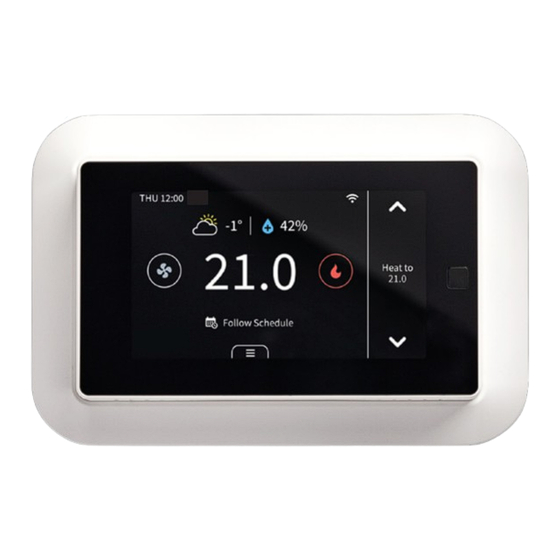
MEET YOUR THERMOSTAT DEVICE OVERVIEW Main Page • Date & Time • Set Point Temperature • Low Sensor Battery Icon • Decrease Temperature • Outdoor Temperature • System Mode • Humidity Status Indicator • Menu & Control Access • Hold Mode •... - Page 40 MEET YOUR THERMOSTAT System Mode • Heat: Heating only Cool: Cooling only • • Auto: Automatic control of heating and cooling based on ambient temperature Off: Turn the system off • W415-4094 / B / 03.19.24...
- Page 41 MEET YOUR THERMOSTAT Weather Click the weather icon on the home page to display the real time outdoor weather condition and temperature for the current day in your home location. NOTE: The weather display screen will indicate the source of the outdoor temperature value.
- Page 42 MEET YOUR THERMOSTAT Humidifier/Dehumidifier • Humidity indicator & temperature control access • + for humidifying • - for dehumidifying • Tap icon to switch between humidity and temperature views • Outdoor humidity (only when viewing humidity controls) • Increase humidity level if humidifier is connected •...
- Page 43 MEET YOUR THERMOSTAT Heating Options Heat Source • Furnace • Heat Pump (select for dual fuel operation outside of Ontario) NOTE: The below settings are only applicable when the heat source selected is Heat Pump: • Min. Heat Pump Outdoor Temperature: When the outdoor temperature is below this temperature, the Heat Pump will not be used.
- Page 44 MEET YOUR THERMOSTAT Hybrid Mode (Ontario only) When Hybrid heating is selected in Menu > System > Heating Options > Heat Source, the heat source used by the system is controlled by the values in the corresponding modes’ switching table. The switching tables can be accessed in Menu > Hybrid Heating.
- Page 45 MEET YOUR THERMOSTAT on according to the ‘Compressor Stage2 Temp Delta’ (non adjustable) and ‘Compressor Stage1 Max Runtime’ (adjustable) and second stage furnace heating will be turned on according to ‘Aux Heat Stage 1 Max Runtime’ in Menu > Settings > Installation > Advanced setting. Green: The values in your green switching table are •...
- Page 46 MEET YOUR THERMOSTAT Hold Mode There are 3 hold modes you can select: Follow Schedule: Follow the settings of schedule to adjust • the temperature, fan, or hybrid mode (if enabled). When you remove hold, the mode will turn to “Follow Schedule”. Permanent Hold: This will always hold the current target •...
- Page 47 MEET YOUR THERMOSTAT Hold temperature until next schedule. Vacation Mode If you are away for a long time, you can set the thermostat to vacation mode in “Menu” -> “Vacation”. You can set the time of departure and return, as well as the highest and lowest temperatures during this period.
- Page 48 MEET YOUR THERMOSTAT Display Here are some changes on the screen and what they mean: When you turn on the compressor frequently, there will be a time countdown to protect the compressor. This will occur in the following case: Heat pump: heating, cooling Conventional: cooling You can set the time countdown in “Menu”...
- Page 49 MEET YOUR THERMOSTAT When the outdoor temperature is below the “Compressor Min Outdoor Temp” you set, the icon on system mode will display and the compressor will be turned off automatically. The thermostat is connected to the router, but the router is not connected to the network.
- Page 50 MEET YOUR THERMOSTAT Menu System • HVAC: Switch system mode (Heat/Cool/Auto/Off) • Fan: Switch fan mode (ON/Auto/Cir) Weather Weather conditions of the real time in your home location. Sensors Add multi-sensors to balance the current temperature throughout the home. Schedule Set schedule to change the temperature automatically.
- Page 51 MEET YOUR THERMOSTAT Lock Multi-level keypad lockout to avoid others tampering with the settings. After locking, the corresponding function is not available and the corresponding settings icon will go dim. An icon with a small lock will appear on top of the main page.
- Page 52 MEET YOUR THERMOSTAT • Advanced Settings 1. Heat/Cool Dissipation Time This is the amount of time the fan will continue to run once the heat/cool is turned off. It will circulate any heated/cooled air remaining in the vents. 2. Compressor Protect Time A timed countdown to protect the compressor from starting too frequently.
- Page 53 MEET YOUR THERMOSTAT Hybrid Heating Set mode to low-cost, comfort, green, or night (see “Hybrid Mode” section for more details). Equipment Reconfigure your wiring setting on thermostat. Equipment Test Test whether the corresponding function of the equipment can run normally as required. •...
-
Page 54: App Overview
APP OVERVIEW Control Page Thermostat Mode: Displays • the current system mode. Tap Thermostat to switch. • Fan Mode: Displays the current fan mode. Tap to switch. • Hold Mode: Displays the current hold mode. Tap to switch. Schedule: Set a schedule •... -
Page 55: Warranty
NAPOLEON warrants the components in your new NAPOLEON product will be free from defects in material and workmanship from the date of purchase, for a period of 3 years. WSC43BA Thermostat WSC-IS Indoor Sensor 3 Years WSC-OS Outdoor Sensor...
Need help?
Do you have a question about the WSC-IS and is the answer not in the manual?
Questions and answers