Table of Contents
Advertisement
Quick Links
Advertisement
Table of Contents

Related Manuals for Gentech SHINERAY GPFW130A


Summary of Contents for Gentech SHINERAY GPFW130A
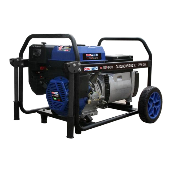
- Page 1 PRODUCT CODES – GPFW130A & GPFW220A...
-
Page 2: Table Of Contents
Instruction Manual Gasoline Welding Generator TABLE OF CONTENTS: GENERAL SAFETY INFORMATION ELECTRICAL SAFETY INFORMATION SAFETY STICKERS AND EXPLANATIONS CONTROL IDENTIFICATION PRE OPERATING INSPECTION STARTING THE ENGINE USING THE GENERATOR USING THE WELDER ACTUAL WELDING... - Page 3 14. TECHNICAL SPECIFICATION AND DATA IMPORTANT: Thank you for purchasing a Gentech Power & Shineray Gasoline Welder Generator (hereinafter referred to as the “welder generator”). This manual will assist you in operating and maintaining your welder generator. This manual is the latest version.
- Page 4 The range of Gentech Power & Shineray Products is safe and reliable, but incorrect use of these products may cause personal injury and or damage to your machine. Please read this manual thoroughly before operation as this product is required to operate strictly in accordance with this manual.
-
Page 5: General Safety Information
This indicates a hazardous situation, which, if not avoided, could result in death or serious injury. Caution CAUTION: This indicates a hazardous situation, which, if not avoided, could result in injury. For any queries on the above please contact GenTech Industries 1. GENERAL SAFETY INFORMATION: Danger Warning Caution... - Page 6 Welder Generator. We recommend that only competent persons should operate the Welder Generator. 1.2. Fuel is combustible and easily ignited. Do not refuel during operation. 1.3. Do not refuel whilst smoking or near naked flames. Do not over fill or spill fuel. If this happens clean the fuel on and around the Welder Generator properly before operating.
-
Page 7: Electrical Safety Information
1.10. Looking at a welding arc may cause damage and or severe pain to your eyes and even possible temporary blindness. DO NOT BE NEGLIGENT. 1.11. Always wear the correct specified gloves when operating the Welder Generator. 1.12. Always wear the correct specified safety shoes/boots when operating the Welder Generator 1.13. - Page 8 circuit breaker that has identical ratings and performance characteristics. 2.5. Due to high mechanical stresses only tough rubber-sheathed flexible cable should be used 2.6. If the Welder Generator is of Class II construction then earthing of the Welder Generator is not required.
- Page 9 than 65m 2.7.5. A 2.5mm2 flexible cable can draw a maximum of 16a provided that the cable is not longer than 45m 2.7.6. A 4mm2 flexible cable can draw a maximum of 10a provided that the cable is not longer than 100m 2.7.7.
- Page 10 No. of Nominal strands Allowable cross A.W.G. Resistance Current Amp. current section strands dia. No./m /100m 0.75 30/0.18 2.477 2.5V 12.5V 1.27 50/0.16 1.486 1.5V 7.5V 37/0.26 0.952 12 to10 45/0.32 0.517 1.5V 2.5V 6.5V 7.5V 10 to 8 70/0.32 0.332 2.5v 3.5V...
-
Page 11: Control Identification
CONTROL IDENTIFICATION:... -
Page 14: Pre Operating Inspection
5. PRE OPERATING INSPECTION: Caution 5.1. Engine Oil – This is a major factor affecting the performance and life span of the Welder Generator. Do not use non-detergent and 2 stroke oil as this will damage the Welder Generator. 5.2. Before using the Welder Generator check the oil level, ensure that the unit is on a flat and level surface when doing this and that the unit is “OFF”... -
Page 15: Starting The Engine
Dirty/contaminated fuel will cause damage to the Welder Generator and will affect the performance. Warning 5.7. Gasoline is extremely flammable, exercise extreme caution when putting fuel into the fuel tank. DO NOT BE NEGLIGENT. 5.8. Always refuel in a well ventilated area. 5.9. -
Page 16: Using The Generator
6.3. Open the fuel cock 6.4. Push the chock lever to the “CLOSED” position Caution Do not use the choke if the engine is warm Caution If using the recoil starter (pull starter) to start the engine be careful as injury may occur due to the sudden change of the rotation direction of the engine. -
Page 17: Using The Welder
7.4. Turn the engine switch to the “ON” position. Warning Do not overload your generator, only load up to the rated power under the rated ambient conditions. Note that operating your generator in extreme humidity and temperatures or in an environment that is not well ventilated will affect the performance and a reduction in power will be noticed. - Page 18 9.1. Selecting the correct welding current: 9.1.2 First measure the thickness of the steel plate that requires welding. Then select the correct electrode diameter and current making reference to the table below: TABLE 1: PLATE THICKNESS (mm) ELECTRODE DIAMETER CURRENT SETTING(A) (mm) 1.6 –...
- Page 19 Always allow a considerable safety margin when selecting welding cable. The life span of the welder will be shortened if the specification cable fails to meet the requirements. TABLE 2: LENGTH (METERS) CABLE GUAGE CABLE SQ (MM2) 15 - 30 30 - 40 CURRENT CAPACITY (AMPERES)
- Page 22 10. STOPPING THE ENGINE: 10.1. Stopping the engine whilst in the “generator” function: 10.1.1.1. Disconnect the load from the AC receptacle 10.1.1.2. Turn the engine switch to the “OFF” position 10.1.1.3. Turn the fuel cock off 10.2. Stopping the engine whilst in the “welder” function: 10.2.1.1.
- Page 23 11.1.1.5. Replace the spark plug if necessary. If the engine will still not start then contact Gentech Industries for technical assistance. The details are on the back page of this operator’s manual. No Electricity/Voltage at the AC Receptacles: 11.2. 11.2.1.1. Check if the over current protector is in the “ON” position. Turn to the “ON” position if necessary.
- Page 25 12. ENGINE OIL: 12.1.1.1. Remove the oil filter cap and check the oil. 12.1.1.2. Remove the drain plug and allow the oil to drain out. Ensure that the oil is drained into a disposable container. 12.1.2. Remove the drain plug and allow the oil to drain out. Ensure that the oil is drained into a disposable container.
- Page 26 12.2.6. If the spark plug is damaged and or very old and dirty we recommend that you replace it. Please ensure that when replacing, it is replaced with the same size. AIR FILTER: 12.3. 12.3.1. Remove the air filter from the air filter casing/cover. 12.3.2.
- Page 27 12.4.6. Install the spark arrestor correctly. 12.4.7. The spark arrestor must be serviced every 100 hours in order to maintain its efficiency. TRANSPORTING AND STORAGE 13.1. Before transporting the Welder Generator please ensure that the fuel cock is in the “OFF” position.
- Page 28 STORAGE TIME RECOMMENDED MAINTENANCE 0 – 1 MONTH NO PREPARATION REQUIRED 1 – 2 MONTHS DRAIN OUT ORIGINAL FUEL IN THE FUEL TANK AND REPLACE WITH CLEAN FUEL 2 – 12 MONTHS DRAIN OUT ORIGINAL FUEL IN THE FUEL TANK AND REPLACE WITH CLEAN FUEL ...
- Page 29 EMPTY FUEL FROM CARBURETOR EMPTY FUEL FROM FUEL SEDIMENT CUP REMOVE THE SPARK PLUG AND POR A TEASPOON OF 4 STROKE ENGINE OIL INTO THE CYLINER. TURN THE ENGINE SLOWLY BY PULLING ON THE RECOIL STARTER. REINSTALL THE SPARK PLUG ...
- Page 30 DRAIN THE CARBURETOR BY LOOSENING THE DRAIN SCREW. DRAIN THE FUEL INTO A SUITABLE CONTAINER. REINSTALL THE DRAIN PLUG. HAVING SWITCHED THE FUEL COCK OFF, REMOVE THE SEDIMENT CUP, EMPTY THE FUEL, THEN REINSTALL THE CUP AND SECURE IT PROPERLY.
- Page 31 14. TECHNICAL SPECIFICATION AND DATA: MODEL GPFW-220A GPFW-130A ENGINE MODEL SR190FE SR170FE DISPLACEMENT CC IGNITION SYSTEM NON CONTACT TRANSISTOR NON CONTACT TRANSISTOR STARTING SYSTEM RECOIL START RECOIL START GENERATOR RATED OUTPUT (KVA) MAX OUTPUT (KVA) RATED VOLTAGE (V) RATED POWER FACTOR (COS) PHASE...
- Page 32 WELDER RATED VOLTAGE (V) 28-30 22-25 CURRENT ADJ. RANGE (A) 50-200 50-130 2.0 – 4.0 ELECTRODE DIAMETER MM 1.6-3.2 WHOLE FUEL TANK CAPACITY (L) MACHINE LXWXH (MM) 810x560x550 715x460x550 NW/GW (KG)
Need help?
Do you have a question about the SHINERAY GPFW130A and is the answer not in the manual?
Questions and answers