
Summary of Contents for M&C MCU1000EX
- Page 1 Electronic Temperature Controller MCU1000EX II 3 G Ex ec nC IIC T4 Gc Instruction Manual Version 1.01.02...
- Page 2 With the release of this version all older manual versions will no longer be valid. The German instruction manual is the original instruction manual. In case of arbitration only the German wording shall be valid and binding. Version: 1.01.02 MCU1000EX | 1.01.02 www.mc-techgroup.com...
-
Page 3: Table Of Contents
Figure 2 Product label MCU1000EX..................................11 Figure 3 Dimensions ........................................12 Figure 4 Mounting the MCU1000EX into a front panel ........................... 13 Figure 5 Electrical connections on the rear: MCU1000EX ........................14 Figure 6 Unlock the device ....................................... 15 Figure 7 Setpoint view ......................................... -
Page 4: General Information
The requirements of the RoHS2 (‘Restriction of Hazardous Substances 2’) directive 2011/65/EU and its annexes are met. Declaration of Conformity The EU Declaration of conformity can be downloaded from the M&C homepage or directly requested from M&C. MCU1000EX | 1.01.02 www.mc-techgroup.com... -
Page 5: Warranty
‘EX‘ indicates important information about the product or about the corresponding parts in the instruction manual, relating to usage in potentially explosive atmospheres. High voltages! Protect yourself and others against damages which might be caused by high voltages. www.mc-techgroup.com MCU1000EX | 1.01.02... -
Page 6: Safety Instructions
INTENDED USE The MCU1000EX is intended to be used as a built-in device for measuring and controlling temperature. Use the device in the permitted range of the electrical and environmental specifications only. See table technical data for details. -
Page 7: Reasonably Foreseeable Misuse
INFORMATION AND SAFETY INSTRUCTIONS FOR USING THE TEMPERATURE CONTROLLER IN HAZARDOUS AREAS The MCU1000EX is suitable for using in hazardous area of zone 2 (see Type Examination Certificate). The explosion proof protection is: II 3G Ex ec nC IIC T4 Gc Type Examination Certificate Number: SIQ 24 ATEX 099 X IECEx Certificate of Conformity Number: IECEx SIQ 24.0001X... -
Page 8: Introduction
APPLICATION The MCU1000EX is a device used for controlling temperature of gas coolers and heaters. The MCU1000EX can be built into front panels of gas cooling devices and heating devices. TECHNICAL DATA Temperature Controller Type MCU1000EX Part No. - Page 9 49 x 32 x 99.5 mm [≈ 1.9" x 1.3" x 3.9"] Weight 80 g [≈ 0.18 lb] *The MCU1000EX needs to be mounted inside a housing or cabinet with protection class IP54 or higher, complying with the IEC 60079-0 standard. www.mc-techgroup.com...
-
Page 10: Description
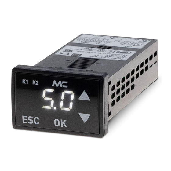
Display for alarm (K1, red LED) or control output Three-digit 7-segment display high/low (K2, yellow LED) ESC and OK button to cancel or confirm a setting UP and DOWN buttons to navigate through the menus Figure 1 LCD display description MCU1000EX | 1.01.02 www.mc-techgroup.com... -
Page 11: Receipt Of Goods And Storage
The controller should be stored in a weather-protected and frost-free area! Note 14.1 PRODUCT LABEL AND SERIAL NUMBER The product label with the serial number is placed on the top of the device. Figure 2 Product label MCU1000EX www.mc-techgroup.com MCU1000EX | 1.01.02... -
Page 12: Dimensions
An explosive free zone is free of explosive atmosphere. The device is completely assembled. It consists of the device body and a mounting frame. To mount the device, the mounting frame needs to be removed from the device body. MCU1000EX | 1.01.02 www.mc-techgroup.com... -
Page 13: Mounting The Temperature Controller
Figure 4 Mounting the MCU1000EX into a front panel VENTILATION REQUIREMENTS There are minimum spacing between panel cut-outs for the MCU1000EX to ensure sufficient ventilation. The minimum spacing of panel cut-outs for tight-to-tight mounting is 15 mm [≈ 0.6"] horizontal and 10 mm [≈ 0.4"] vertical. -
Page 14: Electrical Connections
(over current protection); for electrical details see technical data. To connect the device electrically, use the screw terminals on the back of the housing. Figure 5 Electrical connections on the rear: MCU1000EX Relay Mains voltage may be applied to the relay. The user is responsible for ensuring that the maximum current is not exceeded. -
Page 15: Initial Starting
INITIAL STARTING The MCU1000EX is operated via 4 buttons (OK, ESC, UP and DOWN) and a 3-digit 7-segment display. In the basic state, the display shows the current temperature in °C. 1. Connect the temperature sensor Pt100 to the terminals 12 and 13. Connect the actuator to the control output terminals 10 and 11. -
Page 16: Operating The Device
The setpoint is only visible when the key is touched. Temperature view Jumps back immediately when released Tapping on Setpoint view Figure 7 Setpoint view MCU1000EX | 1.01.02 www.mc-techgroup.com... -
Page 17: Changing The Setpoint
3. Press the OK button to confirm the selection or tap on the ESC key to cancel and leave the configuration menu without selection. 4. Use the UP and DOWN keys to choose the desired value. 5. Confirm the value by pressing on the OK key. www.mc-techgroup.com MCU1000EX | 1.01.02... -
Page 18: Figure 9 Access The Configuration Menu And Set The Codes
The PIN entry is reset approx. 5 minutes after the last button operation or after a restart. Offset correction of Min. -20 °C To adjust the offset of the temperature measurement the temperature Max. 20 °C measurement MCU1000EX | 1.01.02 www.mc-techgroup.com... - Page 19 6 °C – 2 °C - (0.5 x 1 °C) = 3.5 °C, Temperature alarm is resolved at temperatures above 6 °C – 2 °C + (0.5 x 1 °C) = 4.5 °C. www.mc-techgroup.com MCU1000EX | 1.01.02...
-
Page 20: Functional Test
2. After the set point temperature is being reached, the alarm status changes to OK the red LED is extinguished. ERROR MESSAGES Display Cause/remedy or instruction for action Check temperature sensor. If problem persists, send back to M&C Service. MCU1000EX | 1.01.02 www.mc-techgroup.com... -
Page 21: Decommissioning
An explosive free zone is free of explosive atmosphere. The controller MCU1000EX is working maintenance-free for a long period of time. In case the temperature controller is defective, please send the device to M&C TechGroup for repair. -
Page 22: Figure 10 Type Examination Certificate: 1. Page
Figure 10 Type Examination Certificate: 1. Page MCU1000EX | 1.01.02 www.mc-techgroup.com... -
Page 23: Figure 11 Type Examination Certificate: Excerpt From 2. Page
Figure 11 Type Examination Certificate: excerpt from 2. page www.mc-techgroup.com MCU1000EX | 1.01.02... -
Page 24: Figure 12 Iecex Certificate: 1. Page
Figure 12 IECEx Certificate: 1. page MCU1000EX | 1.01.02 www.mc-techgroup.com... -
Page 25: Figure 13 Iecex Certificate: 2. Page
Figure 13 IECEx Certificate: 2. page www.mc-techgroup.com MCU1000EX | 1.01.02... -
Page 26: Figure 14 Iecex Certificate: 3. Page
Figure 14 IECEx Certificate: 3. page MCU1000EX | 1.01.02 www.mc-techgroup.com...
Need help?
Do you have a question about the MCU1000EX and is the answer not in the manual?
Questions and answers