Table of Contents
Advertisement
Quick Links
Super Panel
Sample Set-Ups
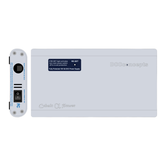
If RE-SET light activates
RE-SET
turn main power switch
off to re-set protection
Fully Protected 18V 5A DCC Power Supply
POWERPRO
NCE Corporation
FROM
CONTROL
CONTROL BUS
BUS
PROGRAM
POWER TRACK
TRACK
STATUS
16VAC / 28VDC MAX.
Point Motor Control
DCC COMMAND STATION
with FIVE AMP POWER BOOSTER
CAB BUS
STATUS TRACK
PH-PRO
Volume One
PUSH
12V DC
CAB OUT
CAB IN
PROGRAM
DCC COMPATIBLE COMMAND CONTROL
LOC:8450 12:54AM
FWD: 000
L-----6
NCE
PROCAB
DIRECTION
MOMENTUM
SPEED
INC FAST
INC
DEC FAST
DEC
HORN/
WHISTLE
BELL
HEADLIGHT
EMERGENCY
STOP
OPTION
RECALL
SELECT
SELECT
LOCO
MACRO
ACCY
1
2
3
4
5
6
7
8
9
0
ENTER
CONSIST
SETUP
CLEAR
ADD
DEL
PROG/
ESC
EXPN
28/128
SHIFT
F10
F11
F12
Advertisement
Table of Contents

Related Manuals for DCCconcepts Super Panel

Summary of Contents for DCCconcepts Super Panel
- Page 1 Super Panel Sample Set-Ups DCC COMPATIBLE COMMAND CONTROL LOC:8450 12:54AM FWD: 000 L-----6 PROCAB If RE-SET light activates RE-SET turn main power switch DIRECTION MOMENTUM off to re-set protection Fully Protected 18V 5A DCC Power Supply SPEED INC FAST DEC FAST...
-
Page 2: Table Of Contents
Connecting a Cobalt S-Lever To Super Panel Connecting Alpha Switch-i To Super Panel & Alpha Mimic Route Setting With 3 Point Motors, 4 Push Buttons and A Super Panel Controlling A Double Slip Using Four Push To Make Switches Controlling Two Separate Solenoid Points Motors Using Two On-Off Toggle Switches DCCconcepts Super Panel Point Motor Control Manual V1.0 May 2024... - Page 3 At the end of each sample we will include a complete parts list of everything we used. Please note, this is by no means the only components you could use, and the benefit of the Super Panel is its ability to interface with various types of switches and components.
- Page 4 Some general ideas to think about before moving on... The inputs on the Super Panel we have picked are just for reference and DO NOT mean you MUST use these! You can use connect ANY input on the Super Panel to control pretty much any DCC accessory.
-
Page 5: Single Point Control Using One On-Off Toggle Switch
Single Point Control Using One On-Off Toggle Switch NCE PCP 13.5V Faceplate PowerCab 12V DC 6pin RJ12 Cable CAB OUT CAB IN Cobalt iP Digital Point Motor Set to Accessory Address 10 DCCconcepts Super Panel Point Motor Control Manual V1.0 May 2024... - Page 6 NCE ProCab Handset PUSH 6pin RJ12 12V DC 6pin RJ12 Cable Flat Cable CAB OUT CAB IN PROGRAM Cobalt iP Digital Point Motor Set to Accessory Address 10 Track/Power Bus DCCconcepts Super Panel Point Motor Control Manual V1.0 May 2024...
- Page 7 BELL HEADLIGHT LOC:8450 12:54AM One thing to note is that the switched input on the Super Panel could be any of the 47 physical FWD: 000 L-----6 inputs, we are just using Input 1 as a starting point, but the switch could easily be connected...
- Page 8 BELL HEADLIGHT We have to tell the Super Panel what the device we are controlling from INPUT 1 is. The point motor is an accessory so press 1, then confirm the accessory number, 10, of the motor by pressing then...
- Page 9 DCC COMPATIBLE COMMAND CONTROL DCC COMPATIBLE COMMAND CONTROL We now need to program the Super Panel to recognise what happens when the switch is in the LOC:8450 12:54AM HIGH or OFF position. We are already on INPUT:1 so to select the high area push the...
- Page 10 SELECT SELECT LOCO MACRO ACCY As before we always finish the command line with an END command, then the Super Panel knows it has reached the end of this particular sequence. So press to select END and press ENTER. Press...
- Page 11 HIGH column when entering data in the LOW column, or vice versa. See the bottom of Page 39 - 7.1 ACCY - 1 = Accessory Number in the full Super Panel User Guide for more information on how to achieve this.
-
Page 12: Dual Point Control Using One On-Off Toggle Switch
PROG/ PUSH 12V DC 6pin RJ12 Cable 6pin RJ12 Flat Cable CAB OUT CAB IN PROGRAM Cobalt iP Digital Point Motor Set to Accessory Address 20 Acce Address Track/Power Bus DCCconcepts Super Panel Point Motor Control Manual V1.0 May 2024... - Page 13 Dual Point Control Using One On-Off Toggle Switch Sample 2 PowerCab Programming Set Up DCC COMPATIBLE COMMAND CONTROL DCC CONCEPTS V1. SUPER PANEL 021 On-Off Toggle Switch connected MOMENTUM DIRECTION to GND & Input 2 SPEED INC FAST DEC FAST...
- Page 14 197 command on the Cobalt iP Digital point motor. You could also get the Super Panel to send out a second command, STEP 2 from INPUT 1 after the first command to change the second point. Make sure you give this second point motor a different Accessory Address, say 21, so it doesn’t respond to STEP 1 of the command structure.
- Page 15 HIGH column when entering data in the LOW column, or vice versa. See the bottom of Page 39 - 7.1 ACCY - 1 = Accessory Number in the full Super Panel User Guide for more information on how to achieve this.
-
Page 16: Controlling Two Separate Points Using Two On-Off Toggle Switches
& Input 3 and 4 13.5V NCE PCP PowerCab Faceplate PUSH 12V DC Cobalt iP Digital 6pin RJ12 Cable CAB OUT CAB IN PROGRAM Point Motor Set to Accessory Address 30 DCCconcepts Super Panel Point Motor Control Manual V1.0 May 2024... - Page 17 6pin RJ12 12V DC Cobalt iP Digital Flat Cable 6pin RJ12 Cable CAB OUT CAB IN PROGRAM Point Motor Set to Set to Accessory Accessory Address 30 Address 31 Track/Power DCCconcepts Super Panel Point Motor Control Manual V1.0 May 2024...
- Page 18 This sample shows how to program two On-Off switches to control two separate point motors. The first On-Off toggle switch is connected with the centre common to one of the Super-Panel ground connections, and the switched connection to Input 3 on the Super Panel. DCC COMPATIBLE COMMAND CONTROL...
- Page 19 HEADLIGHT PROCAB We have to tell the Super Panel what the device we are controlling from INPUT 4 is. The point motor is an accessory so press 1, then confirm the accessory number, 31, of the motor by pressing then...
- Page 20 ENTER to finish these settings. PROCAB Press INP:4 H STEP:1 DIRECTION MOMENTUM DIRECTION NORM/REV : R/2 THEN Press INP:2 H STEP:2 SPEED ENTER INC FAST 1=ACCY 2=MACRO > DEC FAST DCCconcepts Super Panel Point Motor Control Manual V1.0 May 2024...
- Page 21 Track/Power Track/Power Once you become familiar with programming the Super Panel you may find it easier to write out the commands in tabular form so that you can check your logic. This can then be used to input commands to the Super Panel quickly through the NCE keypad - see the next page for the keystrokes tables for SAMPLE 3.
- Page 22 HIGH column when entering data in the LOW column, or vice versa. See the bottom of Page 39 - 7.1 ACCY - 1 = Accessory Number in the full Super Panel User Guide for more information on how to achieve this.
- Page 23 On-Off toggle switches. To add further switches and point motors you just repeat this process, making sure you select the correct input to the Super Panel and the correct digital address for the accessory. DCCconcepts Super Panel Point Motor Control Manual V1.0 May 2024...
-
Page 24: Controlling A 3-Way Point Using Three Push To Make Switches
ENTER CONSIST SETUP CLEAR PROG/ EXPN 28/128 SHIFT 6pin RJ12 Cable 6pin RJ12 Flat Cable Set to Accessory Cobalt iP Digital Address 10 Point Motor Set to Accessory Address 11 DCCconcepts Super Panel Point Motor Control Manual V1.0 May 2024... - Page 25 Cobalt iP Digital PUSH Address 10 Point Motor 12V DC CAB OUT CAB IN PROGRAM Set to Accessory 6pin RJ12 Flat Cable Address 11 ROUTE 1 ROUTE 2 ROUTE 3 Track/Power Bus DCCconcepts Super Panel Point Motor Control Manual V1.0 May 2024...
- Page 26 OPTION RECALL STEP:1 by pressing ENTER: SELECT SELECT Press LOCO MACRO ACCY INPUT:1 LOW STEP: 1 THEN ENTER INP:1 L STEP:1 Press 1=ACCY 2=MACRO > ENTER ENTER CONSIST SETUP CLEAR DCCconcepts Super Panel Point Motor Control Manual V1.0 May 2024...
- Page 27 Then Press ACCY NUMBER:11 Then Press INP:1 L STEP:2 NORM/REV : N/1 Then Press ENTER ENTER ENTER CONSIST CONSIST SETUP CLEAR SETUP CLEAR PROG/ PROG/ DCCconcepts Super Panel Point Motor Control Manual V1.0 May 2024 EXPN 28/128 SHIFT EXPN 28/128 SHIFT...
- Page 28 STOP DCC COMPATIBLE COMMAND CONTROL OPTION RECALL HORN/ WHISTLE BELL HEADLIGHT LOC:8450 12:54AM We always finish the command line with an END command, then the Super Panel knows it has SELECT SELECT EMERGENCY FWD: 000 LOCO MACRO L-----6 ACCY reached the end of this particular sequence. So press to select END and press ENTER.
- Page 29 Select accessory number 11 by pressing 1 and then 1 and then ENTER. SELECT SELECT LOCO MACRO ACCY Press INP:2 L STEP:2 ACCY NUMBER:11 Then Press INP:2 L STEP:2 Then Press NORM/REV : N/1 ENTER ENTER CONSIST SETUP CLEAR DCCconcepts Super Panel Point Motor Control Manual V1.0 May 2024...
- Page 30 Step 15 SELECT SELECT LOCO ACCY MACRO We always finish the command line with an END command, then the Super Panel knows it has DIRECTION MOMENTUM HORN/ reached the end of this particular sequence. So press to select END and press ENTER.
- Page 31 ENTER. PROCAB EXPN 28/128 SHIFT INP:2 L STEP:2 Press DIRECTION MOMENTUM NORM/REV : R/2 DIRECTION Then Press INP:3 L STEP:3 ENTER SPEED INC FAST 1=ACCY 2=MACRO > DEC FAST DCCconcepts Super Panel Point Motor Control Manual V1.0 May 2024...
- Page 32 Track/Power Bus Track/Power Bus Once you become familiar with programming the Super Panel you may find it easier to write out the commands in tabular form so that you can check your logic. This can then be used to input commands to the Super Panel quickly through the NCE keypad - see the next page for the keystrokes tables for SAMPLE 4.
- Page 33 HIGH column, only commands in the LOW commands. See the bottom of Page 39 - 7.1 ACCY - 1 = Accessory Number in the full Super Panel User Guide for more information on this.
- Page 34 Don’t forget, you will also need an NCE system, either a PowerCab or PowerPro, to be able to program and run the Super Panel. You have now configured your Super Panel to control a three way point motor from three separate push to make switches.
- Page 35 CAB BUS STATUS TRACK NCE ProCab PH-PRO Handset PUSH 12V DC 6pin RJ12 Cable CAB OUT CAB IN PROGRAM 6pin RJ12 Flat Cable t iP Digital nt Motor Track/Power Bus DCCconcepts Super Panel Point Motor Control Manual V1.0 May 2024...
-
Page 36: Connecting A Cobalt S-Lever To Super Panel
NCE ProCab PH-PRO Handset PUSH 12V DC 6pin RJ12 Cable CAB OUT CAB IN PROGRAM 6pin RJ12 Flat Cable Cobalt iP Digital Point Motor Set to Accessory Address 10 Track/Power Bus DCCconcepts Super Panel Point Motor Control Manual V1.0 May 2024... - Page 37 HIGH column when entering data in the LOW column, or vice versa. See the bottom of Page 39 - 7.1 ACCY - 1 = Accessory Number in the full Super Panel User Guide for more information on how to achieve this.
- Page 38 Don’t forget, you will also need an NCE system, either a PowerCab or PowerPro, to be able to program and run the Super Panel. You have now configured your Super Panel to control a three way point motor from three separate push to make switches.
-
Page 39: Connecting Alpha Switch-I To Super Panel & Alpha Mimic
STATUS TRACK CAB OUT CAB IN PROGRAM DCC POWER BUS MIMIC LINK C / 28VDC MAX. PH-PRO 6pin RJ12 Cable 6pin RJ12 Flat C Cobalt iP Digital Point Motor Set to DCCconcepts Super Panel Point Motor Control Manual V1.0 May 2024... - Page 40 12V DC CAB OUT CAB IN PROGRAM DCC POWER BUS MIMIC LINK 6pin RJ12 Cable 6pin RJ12 Flat Cable Cobalt iP Digital Point Motor Set to Accessory Address 30 Track/Power Bus DCCconcepts Super Panel Point Motor Control Manual V1.0 May 2024...
- Page 41 DIRECTION MOMENTUM When connecting the Alpha Switch-i to the Super Panel you need to use two switches, one for each SPEED direction of the point motor. The BLACK switch connection is connecting to the GROUND on the INC FAST Super-Panel and the to the required INPUTS - in this case, 11 and 12.
- Page 42 BELL HEADLIGHT We have to tell the Super Panel what the device we are controlling from INPUT 11 is. The point motor is an accessory so press 1, then confirm the accessory number, 30, of the motor by pressing EMERGENCY then and ENTER.
- Page 43 EMERGENCY STOP OPTION RECALL Step 8 DCC COMPATIBLE COMMAND CONTROL HORN/ We always finish the command line with an END command, then the Super Panel knows it has LOC:8450 12:54AM WHISTLE BELL HEADLIGHT SELECT SELECT reached the end of this particular sequence. So press...
- Page 44 EMERGENCY STOP OPTION RECALL We have to tell the Super Panel what the device we are controlling from INPUT 12 is, which is a point motor, so confirm the accessory number, 30, of the motor by pressing then and ENTER.
- Page 45 RECALL DEC FAST Step 15 SELECT SELECT We always finish the command line with an END command, then the Super Panel knows it has LOCO MACRO ACCY reached the end of this particular sequence. So press to select END and press ENTER.
- Page 46 HIGH column, only commands in the LOW commands. See the bottom of Page 39 - 7.1 ACCY - 1 = Accessory Number in the full Super Panel User Guide for more information on this.
- Page 47 1 x Left or Right hand point - various makes can be used Various cable and connectors Don’t forget, you will also need an NCE system, either a PowerCab or PowerPro, to be able to program and run the Super Panel. DCCconcepts Super Panel Point Motor Control Manual V1.0 May 2024...
- Page 48 Set to 12V DC Accessory Accessory CAB OUT CAB IN PROGRAM Address 21 Address 22 6pin RJ12 Flat Cable alt iP ital ROUTE 4 ROUTE 3 ROUTE 2 ROUTE 1 DCCconcepts Super Panel Point Motor Control Manual V1.0 May 2024...
-
Page 49: Route Setting With 3 Point Motors, 4 Push Buttons And A Super Panel
Route Setting With 3 Point Motors, 4 Push Buttons and A Super Panel Sample 7 PowerCab Programming Set Up DCC COMPATIBLE COMMAND CONTROL DCC CONCEPTS V1. Push to make SUPER PANEL 021 switches connected to GND and 1, 2, 3 & 4... - Page 50 Before we start programming the Super Panel we need to work out a logic table for the direction of each point motor with each button push to each required route. It would not be difficult to add LED indication to a control panel as well, but more on that in a later guide.
- Page 51 ENTER to save these settings. EXPN 28/128 SHIFT INP:1 L STEP:1 NORM/REV : N/1 ENTER Press ENTER CONSIST INP:1 L STEP:2 SETUP CLEAR 1=ACCY 2=MACRO > PROG/ EXPN 28/128 SHIFT DCCconcepts Super Panel Point Motor Control Manual V1.0 May 2024...
- Page 52 EMERGENCY STOP OPTION RECALL Step 6 We always finish the command line with an END command, then the Super Panel knows it has SELECT SELECT LOCO MACRO ACCY reached the end of this particular sequence. So press to select END and press ENTER.
- Page 53 SHIFT CONSIST SETUP CLEAR INP:2 L STEP:2 NORM/REV : R/2 ENTER PROG/ Press EXPN 28/128 SHIFT ENTER CONSIST INP:2 L STEP:3 SETUP CLEAR 1=ACCY 2=MACRO > PROG/ EXPN 28/128 SHIFT DCCconcepts Super Panel Point Motor Control Manual V1.0 May 2024...
- Page 54 EMERGENCY STOP OPTION RECALL Step 13 We always finish the command line with an END command, then the Super Panel knows it has SELECT SELECT reached the end of this particular sequence. So press to select END and press ENTER.
- Page 55 INP:3 L STEP:2 STOP OPTION RECALL MOMENTUM DIRECTION DIRECTION NORM/REV : N/1 THEN SELECT SELECT Press LOCO MACRO ACCY INP:3 L STEP:3 SPEED INC FAST ENTER 1=ACCY 2=MACRO > DEC FAST DCCconcepts Super Panel Point Motor Control Manual V1.0 May 2024...
- Page 56 INC FAST 1=ACCY 2=MACRO > EMERGENCY STOP OPTION RECALL DEC FAST Step 22 ENTER We always finish the command line with an END command, then the Super Panel knows it has SELECT SELECT HORN/ LOCO MACRO ACCY WHISTLE BELL HEADLIGHT reached the end of this particular sequence.
- Page 57 ENTER to save these settings. EXPN 28/128 SHIFT INP:4 L STEP:1 MOMENTUM DIRECTION NORM/REV : R/2 Press ENTER INP:4 L STEP:2 SPEED INC FAST 1=ACCY 2=MACRO > DEC FAST DCCconcepts Super Panel Point Motor Control Manual V1.0 May 2024...
- Page 58 EXPN 28/128 SHIFT Press INP:4 L STEP:3 MOMENTUM DIRECTION DIRECTION NORM/REV : N/1 THEN Press INP:4 L STEP:4 SPEED INC FAST ENTER 1=ACCY 2=MACRO > DEC FAST DCCconcepts Super Panel Point Motor Control Manual V1.0 May 2024...
- Page 59 EMERGENCY STOP OPTION RECALL Step 31 We always finish the command line with an END command, then the Super Panel knows it has SELECT SELECT reached the end of this particular sequence. So press to select END and press ENTER.
- Page 60 1, 20, ENTER, 2, ENTER Accessory 20 Reverse Not Needed 1, 21, ENTER, 1, ENTER Accessory 21 Normal Not Needed 1, 22, ENTER, 2, ENTER Accessory 22 Reverse Not Needed 0, Enter Not Needed DCCconcepts Super Panel Point Motor Control Manual V1.0 May 2024...
- Page 61 HIGH column, only commands in the LOW commands. See the bottom of Page 39 - 7.1 ACCY - 1 = Accessory Number in the full Super Panel User Guide for more information on this.
-
Page 62: Controlling A Double Slip Using Four Push To Make Switches
PROG/ CAB BUS EXPN 28/128 SHIFT STATUS TRACK PH-PRO ProCab Handset 6pin RJ12 Cable PUSH 12V DC gital CAB OUT CAB IN PROGRAM 6pin RJ12 Flat Cable Set to Accessory DCCconcepts Super Panel Point Motor Control Manual V1.0 May 2024... - Page 63 CAB OUT CAB IN PROGRAM Point Motor 6pin RJ12 Flat Cable Set to Accessory Set to Address 30 Accessory Address 31 ROUTE 1 ROUTE 3 ROUTE 2 ROUTE 4 Track/Power Bus DCCconcepts Super Panel Point Motor Control Manual V1.0 May 2024...
- Page 64 OPTION RECALL STEP:1 by pressing ENTER: SELECT SELECT Press LOCO MACRO ACCY INPUT:1 LOW STEP: 1 THEN ENTER INP:1 L STEP:1 Press 1=ACCY 2=MACRO > ENTER ENTER CONSIST SETUP CLEAR DCCconcepts Super Panel Point Motor Control Manual V1.0 May 2024...
- Page 65 OPTION RECALL HORN/ WHISTLE BELL HEADLIGHT We always finish the command line with an END command, then the Super Panel knows it has SELECT SELECT reached the end of this particular sequence. So press to select END and press ENTER.
- Page 66 RECALL DEC FAST Step 10 SELECT SELECT We always finish the command line with an END command, then the Super Panel knows it has LOCO MACRO ACCY reached the end of this particular sequence. So press to select END and press ENTER.
- Page 67 RECALL DEC FAST Step 14 SELECT SELECT We always finish the command line with an END command, then the Super Panel knows it has LOCO MACRO ACCY reached the end of this particular sequence. So press to select END and press ENTER.
- Page 68 RECALL DEC FAST Step 18 SELECT SELECT We always finish the command line with an END command, then the Super Panel knows it has LOCO MACRO ACCY reached the end of this particular sequence. So press to select END and press ENTER.
- Page 69 Once you become familiar with programming the Super Panel you may find it easier to write out the commands in tabular form so that you can check your logic. This can then be used to input commands to the Super Panel quickly through the NCE keypad - see below for the keystrokes table for SAMPLE 8.
- Page 70 HIGH column, only commands in the LOW commands. See the bottom of Page 39 - 7.1 ACCY - 1 = Accessory Number in the full Super Panel User Guide for more information on this.
- Page 71 1 x Double Slip - various makes can be used Various cable and connectors Don’t forget, you will also need an NCE system, either a PowerCab or PowerPro, to be able to program and run the Super Panel. DCCconcepts Super Panel Point Motor Control Manual V1.0 May 2024...
- Page 72 Flat Cable CAB OUT CAB IN PROGRAM Accessory Decoder CDU Solenoid Drive Set to Set to RUN SET DC or DCC 12V TO 20V Accessory Accessory Address 50 Address 51 DCCconcepts Super Panel Point Motor Control Manual V1.0 May 2024...
-
Page 73: Controlling Two Separate Solenoid Points Motors Using Two On-Off Toggle Switches
Accessory Decoder CDU Solenoid Drive Set to Set to RUN SET DC or DCC 12V TO 20V Accessory Accessory Solenoid Address 50 Address 51 Point Motor Solenoid Track/Power Bus Point Motor DCCconcepts Super Panel Point Motor Control Manual V1.0 May 2024... - Page 74 CLEAR First we set what the switch will do when it is LOW or ON, so leave the LO/HI at L. Next select INPUT:13, the Super Panel input you have connected the switched terminal from the toggle switch EMERGENCY PROG/...
- Page 75 Press ENTER INP:13 L STEP:2 Q SEC COUNT: 4 ENTER Press CONSIST INP:13 L STEP:3 SETUP CLEAR Press 1=ACCY 2=MACRO > ENTER PROG/ EXPN 28/128 SHIFT DCCconcepts Super Panel Point Motor Control Manual V1.0 May 2024...
- Page 76 Step 9 FWD: 000 L-----6 MOMENTUM DIRECTION We now need to set the HIGH commands, or what the Super Panel does when the switch is PROCAB switched off. So, press the DIRECTION key to select the high commands and press ENTER.
- Page 77 PROG/ OPTION RECALL EXPN 28/128 SHIFT Step 14 We always finish the command line with an END command, then the Super Panel knows it has SELECT SELECT LOCO MACRO ACCY reached the end of this particular sequence. So press to select END and press ENTER.
- Page 78 HIGH column when entering data in the LOW column, or vice versa. See the bottom of Page 39 - 7.1 ACCY - 1 = Accessory Number in the full Super Panel User Guide for more information on how to achieve this.
- Page 79 Various cable and connectors Don’t forget, you will also need an NCE system, either a PowerCab or PowerPro, to be able to program and run the Super Panel. You have now configured your Super Panel to control two solenoid point motor from 2 Channel Accessory Decoder using 2 toggle switches.
Need help?
Do you have a question about the Super Panel and is the answer not in the manual?
Questions and answers
I **** wanting to control legacy occupancy detectors 50x units can you use a super panel for this
No, the DCCconcepts Super Panel has 50 inputs, but these inputs are not specifically stated to support 50 legacy occupancy detectors. The document mentions that the accessory decoder is used to read the status of five block detectors, but it does not confirm compatibility with 50 legacy occupancy detectors.
This answer is automatically generated