
Summary of Contents for UFO Sirius-S Series
- Page 1 PRODUCT USER GUIDE Sirius-S White Light Source Range Rev: C6 PLEASE READ THIS USER GUIDE BEFORE INSTALLING OPERATING OR PERFORMING MAINTENANCE ON THE LIGHT SOURCE UNIT...
- Page 2 INTRODUCTION Thank you for purchasing this UFO light source. To ensure that the light source is set up optimally and gives a long service life, please read this user guide before installing, operating or performing any maintenance on the unit.
- Page 3 Warning: The luminaire should be positioned so that staring into the luminaire at a distance closer than 2.7 metres is not expected. UFO will accept no liability for damage, or associated claims, caused by not following the installation and safety instructions contained within this user guide.
-
Page 4: Installation
INSTALLATION MODEL TYPES The Sirius-S LED light source incorporates a range of LED arrays to provide optimum display and illumination within the following optical range. Model Colour Temperature Lumen Output UFO SIRS2280 >80 2200K 10117 UFO SIRS2780 >80 2700K 12517 UFO SIRS3080 >80... - Page 5 Plug the IEC connector into the IEC socket and then plug the mains connector into a local mains supply. Switch on power the mains indicator will illuminate and the light source is ready for use. If no light is produced consult the TROUBLESHOOTING section in this manual. UFO LIGHTING...
- Page 6 INSTALLATION CONNECTION FOR REMOTE MANUAL OPERATION This connection method allows the luminaire to be dimmed remotely using a simple passive potentiometer control. There are three connections required – the fibre port, the remote dimmer cable and the mains supply cable. The fibre port should be connected first before the mains supply. Connect and secure the fibre optic connector into the collar and the front of the unit and secure using the M5 knurled locking screw.
- Page 7 • Use a 10kΩ linear potentiometer connected across pins 4, 5 and 7 as detailed on page 6. See Accessories in Technical Specification section at end of this document for UFO CVD1 • The CVD1 is designed to be fitted to the back of a one gang faceplate...
- Page 8 INSTALLATION CONNECTION FOR DMX REMOTE CONTROL OPERATION There are three connections required – the fibre port, the DMX cables and the mains supply cable. The fibre port should be connected first before the mains supply. Connect and secure the fibre optic connector into the collar and the front of the unit and secure using the M5 knurled locking screw.
- Page 9 • Always use an approved CAT5 cable • Ensure correct connection polarity at all times • See Accessories in Technical Specification section at end of this document for UFO CVD3 compliant dimmer • The CVD3 is designed to be fitted to the back of a one gang faceplate...
- Page 10 INSTALLATION FOR 0 10 V ( CURRENT SOURCE ) OPERATION CONNECTION There are three connections required – the fibre port, the 0-10V cables and the mains supply cable. The fibre port should be connected first before the mains supply. Connect and secure the fibre optic connector into the collar and the front of the unit and secure using the M5 knurled locking screw.
- Page 11 • This is a current source 0-10V control system. The input from the 0-10V controller (source) supplies a varying control voltage between 0 and 10V to the luminaire to control dimming. • Always use an approved CAT5 cable • With no 0-10V input the luminaire will give no light output UFO LIGHTING...
- Page 12 INSTALLATION FOR MASTER / SLAVE OPERATION CONNECTION There are three connections required – the fibre port, the DMX cables and the mains supply cable. The fibre port should be connected first before the mains supply. Connect and secure the fibre optic connector into the collar and the front of the unit and secure using the M5 knurled locking screw.
-
Page 13: Operation
: Once programmed the luminaire will always revert to the programmed IMPORTANT NOTE settings when power is recycled. However, if manual RESET is selected the luminaire will revert to factory default settings as detailed below: White Light Standard & Emergency Dimming 100%/DMX address 001/Control Mode Master UFO LIGHTING... - Page 14 OPERATION PROGRAMMABLE FUNCTION TABLE SiriusS Model Version Main Menu Sub Menu Description Instructions Use + & buttons to Standard White Light DMX Address None Sets DMX address display chosen address. Press enter to select Allows manual control Press enter button to Standard White Light Control Mode Master of light source...
-
Page 15: Manual Operation
0100% dimming across range Normal LED & fan on White Light 0120 LED illuminated & fan running Initialise/Reset White Light 121200 Initialise starts if held on for 10 secs Switch LED & fans off White Light 201255 LED off immediately, fans after 30 secs UFO LIGHTING... - Page 16 OPERATION 1-10 V OPERATION Only Sirius-S standard white light models can be 1-10V (current sink) dimmed as detailed in the Programmable Function Table in the preceding section and in the following sections. NOTE: • For all 1-10v current sink dimming the luminaire must be set to 1-10V in the Control Mode sub menu.
-
Page 17: Master/Slave Operation
DMX Slave address must be set using the DMX Address menu to address 001. • Once the master and Slaves have been set up as above, the Slaves will follow all the manual functions of the Master. UFO LIGHTING... -
Page 18: Safety Guidance
MAINTENANCE AND SAFETY GUIDANCE MAINTENANCE To ensure a long working life and the safe, reliable operation of the light source, it is very important to maintain it properly and ensure it is installed in an appropriate and safe location. Before performing any maintenance on the light souce it should be disconnected from the power supply and allowed to cool down. -
Page 19: Troubleshooting
& LCD display is out IEC blown fuse Check fuse & replace if necessary Mains supply cable faulty Get replacement cable from UFO Select dim level option & manually set Unit in Master mode & dimming at 0% dimming level ALL MODELS Unit in 010V mode, but no control... - Page 20 110V MODELS Dim level changes with remote Incompatible current sink dimmer Contact UFO dimming, light out put range inaccurate or reduced Check 010V control voltage at controller & Unit in 010V control mode but no 010V ...
-
Page 21: Technical Specification
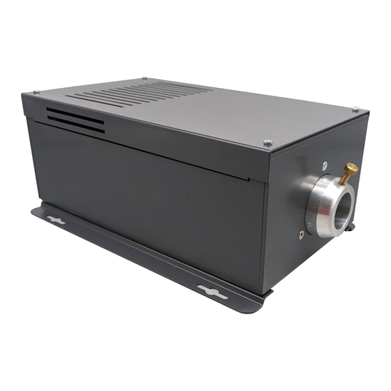
2 Channels. User addressable to 512 LED Life 50,000 hours typical Operating Environment Indoor / dry Min Ambient Temperature 10°C Max Ambient Temperature +45°C Material Aluminium Finish Grey Powdercoat (RAL7024) Dimensions (L x W x H) 280mm (11”) x 190mm (7.5”) x 118mm (4.6”) UFO LIGHTING... - Page 22 ADDITIONAL MAINTENANCE RECORD MAINTENANCE LOG Date Maintenance Undertaken SIRIUS S USER GUIDE...
- Page 23 NOTES UFO LIGHTING...
- Page 24 United Kingdom • United States • Germany • Europe • Universal Fibre Optics Ltd Universal Fiber Optics USA LLC UFO Licht GmbH Home Place Coldstream 1749 Northgate Blvd Andreasstraße 20 TD12 4DT Sarasota FL34234 93059 Regensburg Deutschland +49 (0)9491 955880...
Need help?
Do you have a question about the Sirius-S Series and is the answer not in the manual?
Questions and answers