Advertisement
Quick Links
RW1300-110APO
REACH Sndr Base
I MPORTANT TO CONSIDER
When mounting a wireless device, a comprehensive radio survey
should have been carried out to establish the location that provides
the best coverage and optimum reach. Taking into consideration the building
structure and materials, the survey identifies the wireless infrastructure
required and product locations for optimum performance, identifying
any factor that could prevent radio integrity.
Avoid fixing or mounting the unit close to the following:
• Equipment that utilises large electrical currents
• Large metal objects or structures
• Fluorescent lighting fittings
• Metal ceiling structures
• I T cabling.
Keep 2 meters minimum spacing between other wireless equipment
in the area to avoid signal interference.
EN54 approved environmental temperature range is -10°C to +55°C
UNBOXING
• When unboxing the Sounder Base you will find the unit and its mounting base.
• This comes with pre-formed mounting holes to mount the mounting base.
• A securing screw is fitted to ensure unwanted removal of the attached device.
• Two screws are supplied to fix the sounder to the mounting base
(optional)can be used to fix the battery cover, when the base is topped by the lid.
• DIP switches are found inside the sounder to select your desired tone and volume.
For more information, please refer to the user manual. Available on apollo-fire.co.uk
Apollo Fire Detectors Ltd. 36 Brookside Road, Havant, Hampshire, United Kingdom, PO9 1JR
T: +44 (0)23 9244 2706 - E: techsales@apollo-fire.com - W: www.apollo-fire.co.uk
RW1300-110APO
REACH Sndr Base
QUI CK START GUI DE
THE BOX
INSIDE THE BOX
• 1 x Sounder Base
Product Part Number
Product Description
• 2 x CR123A batteries
• 3 x Screws
• 1 x Battery cover
• 1 x Quick start guide
Scan QR code
for full user manual
and one screw
RW1300-160APO
REACH Sndr Base – BK Bdy
MOUNTING STEPS
Proceed as follows to complete the device installation.
Remove the mounting base from the sounder.
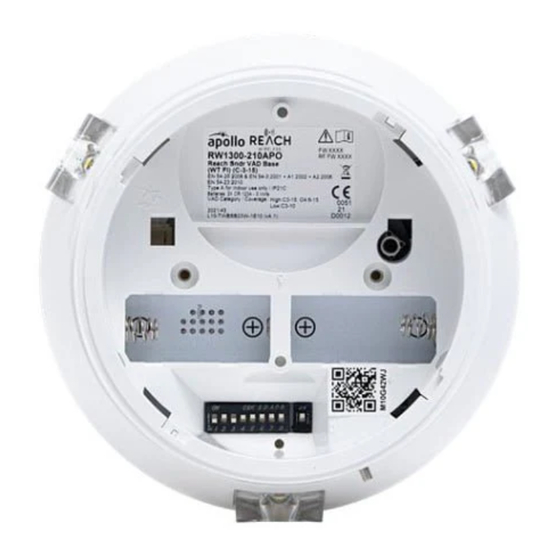
FI XI NG
HOLES
TONE
AND VOLUME
SELECTI ON
BATTERY
COMPARTMENT
COVER
• Put the sounder back onto the mounting base and secure
Remove the battery compartment cover on the base.
with the two screws supplied.
• Select the tone and volume you require (see next page)
• Ensure the programming switch in the base of the sounder
is in position ON.
BATTERY
BATTERY A
BATTERY A
BATTERY B
BATTERY B
COMPARTMENT
LODGEMENT
LODGEMENT
LODGEMENT
LODGEMENT
COVER
LED I NDI CATOR
LED I NDI CATOR
• Ensure switch on position.
• Ensure switch on position.
• Fit the 2x CR123A batteries ensuring you have checked
• Fit the 2x CR123A batteries ensuring you have checked
they are the correct way round observing the polarity
they are the correct way round observing the polarity
indications on the base of the sounder base.
indications on the base of the sounder base.
• The LED will signal 4 times red.
• The LED will signal 4 times red.
FIXING HOLE FOR
• Move the switch in the base of the sounder base to position 1.
• Move the switch in the base of the sounder base to position 1.
OPTIONAL SCREW
• The LED will blink few seconds green and then signal
• The LED will blink few seconds green and then signal
alternatively green/red 4 times.
alternatively green/red 4 times.
Remove the battery compartment cover on the base.
• Ensure you replace the battery cover as this forms part
• Ensure you replace the battery cover as this forms part
Fit the battery compartment cover on the base.
of the sounder base anti tamper protection.
of the sounder base anti tamper protection.
1
MOUNTI NG
HOLES
• Locate the mounting holes and mark them using a pencil
on the desired surface your are drilling.
• Using a suitable-sized drill bit (6 mm) drill the marked
screw points on your chosen surface.
• Ensure you use the correct fixings for the type of surface
you are mounting to.
• Screw the base to the ceiling using all fixing holes and
appropriate-sized screws.
3
FI XI NG
HOLES
BATTERY A
LODGEMENT
TONE
TONE
AND VOLUME
AND VOLUME
SELECTI ON
SELECTI ON
• Fit the 2x CR123A batteries ensuring you have checked
PROGRAMMI NG
they are the correct way around observing the polarity
SWI TCH
indications on the base of the sounder base.
• The LED will signal 4 times red.
• Move the switch in the base of the sounder base to position 1.
• Put the sounder back onto the mounting base and secure
• Put the sounder back onto the mounting base and secure
• The LED will blink few seconds green and then signal
with the two screws supplied.
with the two screws supplied.
alternatively green/red 4 times.
• Select the tone and volume you require (see next page)
• Select the tone and volume you require (see next page)
• Ensure you replace the battery cover as this forms part
• Ensure the programming switch in the base of the sounder
• Ensure the programming switch in the base of the sounder
of the sounder base anti
tamper protection.
-
is in position ON.
is in position ON.
5
• Fit the detector or the blanking cap to the top of the
device and secure the safety screw using a M3 allen key.
RW_QSG_AV_BASE_SNDR_REV_A.9
2
4
BATTERY B
LODGEMENT
LED I NDI CATOR
PROGRAMMI NG
PROGRAMMI NG
SWI TCH
SWI TCH
6
Advertisement

Summary of Contents for Reach apollo RW1300-110APO
- Page 1 • Screw the base to the ceiling using all fixing holes and the best coverage and optimum reach. Taking into consideration the building appropriate-sized screws. structure and materials, the survey identifies the wireless infrastructure...
- Page 2 RW1300-110APO RW1300-160APO REACH Sndr Base REACH Sndr Base – BK Bdy QUI CK START GUI DE TONE AND VOLUME SELECTION Use the DIP switch on Primary Tone (Evacuation) Secondary Tone (Alert) the back of the Apollo Tone DIP Switch Pair Number...
Need help?
Do you have a question about the apollo RW1300-110APO and is the answer not in the manual?
Questions and answers