Table of Contents
Advertisement
Quick Links
Advertisement
Table of Contents

Summary of Contents for ELNet LTC
- Page 1 Installation & Operation Manual Elnet Power Factor Controller...
-
Page 2: Table Of Contents
Table of Contents CHAPTER 1 – Electrical Wiring ...........3 Electrical Connections..........3 Electrical Wiring Diagrams........5 Indication Leds.............7 Test Capacitors Screen..........8 CHAPTER 2 – Power Factor Controller.........10 General Information............10 Controller's Data Screen..........12 CHAPTER 3 – Power Factor Controller Settings......13 Transformers Ratio............13 Vital Settings..............16 Non Vital Settings.............21 Working Range..............23... -
Page 3: Chapter 1 - Electrical Wiring
CHAPTER 1 – Electrical Wiring 1.1. Electrical connections All Connections, except those to the CT core of the ElNet LTC Power Factor Controller are made via terminal connector plugs. Recommended max tightening torque for the connector screws is 0.5 Nm. - Page 4 Insert the lead from side “K” of the Current Transformers of Line 1 through the hole marked "I1" – "K" of the ElNet LTC Power Factor Controller. WARNING Repeat the procedure for Line 2 and Line 3 ("I2""I3"/"K"). Connect the rest of the connections to the ElNet LTC Power Factor Controller by means of terminal connector plugs.
-
Page 5: Electrical Wiring Diagrams
Figure 1.1 – Three Phase Electrical wiring diagram... - Page 6 Pin Designation Description Remarks Line 1 - Voltage Supply Use 6Amp fuse to protect the line Use 6Amp fuse to Line 2 - Voltage Supply protect the line Use 6Amp fuse to Line 3 - Voltage Supply protect the line Neutral Measurement neutral Line...
-
Page 7: Indication Leds
In the front panel of the Elnet LTC located 16 indication Leds. Each Led is marked according to the relay output number of the LTC. When the LTC turns on one of its outputs, the relevant Led will turn on accordingly, to indicate which capacitor is on. -
Page 8: Test Capacitors Screen
1.4. Test Capacitors Screen From the Main Menu scroll to TECHINCAL and press "Enter". Figure 1.4 – Access the Settings screen The ENTER CODE screen appears. Figure 1.5 – Enter Code screen The password to activate the Test Relay screen is 789. Use the buttons F3 &... - Page 9 The TEST CAP screen will appear. Figure 1.6 – Test Capacitors screen Use the navigation buttons to scroll, force and release the relevant output. When finished press "Back" to return to the main menu.
-
Page 10: Chapter 2 - Power Factor Controller
In addition the Elnet LTC can also measure Energy, Power Quality - all the features of Elnet LT energy & power meter. (For detailed information of how to operate and use Elnet LT features please check the attached Elnet LT manual. - Page 11 2. The POWER, POWER FACTOR screen appears. Figure 2.2 – Power, Power Factor screen 3. Scroll to "PF Controller", and press "Enter". The PF CONTROLLER screen appears. Figure 2.3 – PF Controller screen...
-
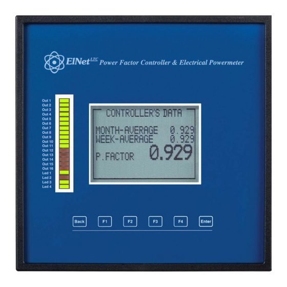
Page 12: Controller's Data Screen
2.2 Controller's Data Screen. Selection of "CONTROLLER'S DATA" from the main menu displays monthly and weekly average power factor (from the last power startup) and also real time power factor. In case of fault one of the following messages appears: "... -
Page 13: Chapter 3 - Power Factor Controller Settings
CHAPTER 3 – Power Factor Controller Settings In order to set all values requested for proper operation of the Power Factor Controller, the following settings must be defined: Transformer Ratio, Vital Setting, Non Vital Setting & Working Range. 3.1 Transformers Ratio. From Main Menu scroll to TECHNICAL and press "Enter", The Enter Code screen appears. - Page 14 NOTE! If the incorrect password is inserted into the Password field, an Error message appears and the password should be reentered The TECHNICAL screen appears. Figure 3.2 – Technical screen Scroll to "Transformer Ratio" and press "Enter". The Transformer Ratio screen appears.
- Page 15 In order to set the Current Transformers ratio, scroll to Current Trans and press "Enter". Figure 3.3 – Transformer Ratio. The Current Transformer screen appears. Figure 3.4 – Changing Transformer Ratio. Use the buttons F3 & F4 to move the cursor, to set the value use buttons F1 &...
-
Page 16: Vital Settings
In order to set the Voltage Transformers ratio, scroll to Voltage Trans and press "Enter". Use the buttons F3 & F4 to move the cursor, to set the value use buttons F1 &F2, when finished click “ENTER”. 3.2 Vital Setting. In order to define the Vital Setting, you must access the PF CONTROLLER screen by repeating steps from chapter 2, paragraphs 1,2,3. - Page 17 3.2.1 Setting the Power Factor Set Point: Scroll down to Power Factor and press "Enter". The Power Factor setting screen appears. Figure 3.6 – Power Factor change. Use the buttons F3 & F4 to move the cursor, to set the value use buttons F1 &F2, when finished click “ENTER”.
- Page 18 There are a number of methods as following: "RANDOM" - this method enables random selection of equally- sized capacitors. In this method after a certain period, the number of the working hours, of all equally-sized capacitors will be equal. "FIRST" - this method enables fixed selection, meaning a certain capacitor will always be first and the other will always be second and third and so on –...
- Page 19 F4 to move the cursor, to set the value use the buttons F1 & F2, when finished click “ENTER”. 3.2.4 Capacitor's Value measure: The Elnet LTC enables true capacitors value measure for capacitors 1 up to 16. In order to measure and automatically define the values of the capacitors which are used in the system, at the Vital Setting screen scroll down to Capacitors Measure, and press "Enter".
- Page 20 Once the Value Measure screen appeared, the LTC will automatically begin measuring process. It will scan and measure each capacitor step, one by one, the whole process may take a few minutes. (During the scan process the indications Output Leds will turn On according to the scanned output progress).
-
Page 21: Non Vital Settings
3.3 Non-vital setting In order to define the Non Vital Setting, you must access the PF CONTROLLER screen by repeating steps from chapter 2, paragraphs 1,2,3. Once the PF CONTROLLER screen appears, scroll to Non Vital Setting and press "Enter". The Non Vital Setting screen appears. - Page 22 3.3.2 "DELAY OFF": Delay Off enables setting the delay (seconds) between the decision of disconnecting the capacitor and its actual disconnection. This delay is meant to minimize the number of connections/disconnections of the capacitors during control of the desired power factor value. In order to change delay off , scroll to DELAY OFF and press "Enter".
-
Page 23: Working Range
3.3.4 "DELAY ERR": Delay ERR enables setting the delay (seconds) after an error accurse (for error list please check chapter 2.2) and between the return to normal operation mode. This delay is meant to minimize the number of connections/disconnections of the capacitors during control of the desired power factor value. - Page 24 Once the PF CONTROLLER screen appears, scroll to Working Range and press "Enter". The Working Range screen appears. Figure 3.10 – Working range settings. 3.4.1 "MAX. THD I" setting: Enables disconnection of all the capacitors whenever the actual THD I value exceeds the value which was defined by the user.
- Page 25 3.4.2 "MAX. THD V" setting: Enables disconnection of all the capacitors whenever the actual THD V value exceeds the value which was defined by the user. When THD V = 0 this option is disabled. In order to change the Max. THD-V, scroll to Max. THD-V line and press "Enter".
- Page 26 Use the buttons F3 & F4 to move the cursor, to set the value use buttons F1 & F2, when finished click “ENTER”. 3.4.5 "MAX. VOLTAGE" setting: Enables defining voltage high limit value, above this value all the capacitors will be disconnected. In order to change the Max.
Need help?
Do you have a question about the LTC and is the answer not in the manual?
Questions and answers