Advertisement
Quick Links
Advertisement

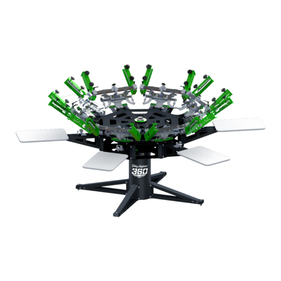
Summary of Contents for Riley Hopkins 360
- Page 1 Assembly Instructions...
- Page 2 Qty. MAIN PRESS CORE (BACK CLAMP MODEL SHOWN) 1 PER UNIT PLATEN ASSEMBLY 1 PER STATION PRINT STATION (RILEY HOPKINS SHOWN) 1 PER STATION HARDWARE KIT 1 PER UNIT 1 RH & 1 LH per SIDE CLAMP ASSEMBLY (SIDE CLAMP MODELS ONLY)
- Page 3 PRSA-RHCLRARMKIT RILEY 360 PRINT HEAD STOP BOLT KIT-PER HEAD NAME/ID DESCRIPTION Qty. AIR HOSE FOR RILEY PRINT HEAD BUMP PRCO-BMPRBLTCVRBLU STOPS 3-1/2” LONG PRHD-WA3/8SAE-SS 3/8 SAE FLAT WASHER STAINLESS STEEL PRHD-HC3/8NF4- 3/8-24 X 4-1/2” HEX CAP SCREW GRADE 1/2GR5ZC 5 ZINC...
- Page 4 PRSA-RHPSKIT RILEY 360 PRINT STATION HARDWARE-PER STATION NAME/ID DESCRIPTION Qty. 3/8-16 X 1 HEX CAP SCREW GRADE 5 PRHD-NYN3/8NCGR5ZC ZINC PRHD-NYN3/8NCGR5ZC 3/8-16 NYLOC NUT ZINC PRHD-WA5/16USSGR5ZC 5/16 USS FLAT WASHER ZINC PRHD-RP3/16X1ZC 3/16 X 1 ROLL PIN ZINC...
- Page 5 STEP 1 Install the lower bumper bolt assemblies. Do not overtighten hardware. Tighten just enough to hold in place. NOTE: Refer to RHCLRARMKIT for hardware detail Before dropping the print heads, ensure that spring hooks are engaged in the slots. The hooks must be facing upward. WARNING: EXTREME FORCE. INSTALL WITH CAUTION!
- Page 6 STEP 2 Drop printhead into the down position, resting on the lower stop bolt previously installed. Install the Upper bumper bolt assemblies. Do not overtighten hardware. Tighten just enough to hold in place. NOTE: Refer to RHCLRARMKIT for hardware detail.
- Page 7 Do not fully tighten at this time. They must be snug but loose enough to adjust with bumps of the hand. Riley Hopkins arm shown. ROQ compatible arms will follow the same process using the outer set of mounting holes.
- Page 8 Tap them in approx. ½” with a hammer. After pins are seated, fully tighten the print station hardware. Riley Hopkins arm shown. ROQ compatible arms will follow the same process. Note: Refer to RHPSKIT for hardware detail.
- Page 9 STEP 5 Install the platens onto the print stations. Set the platen (1) in the desired position. To lock in place, first tighten the side knob (2). Then tighten the lower knobs (3).
- Page 10 STEP 6 ROQ Compatible Station Arms To install the platens (1) into the print station, Align the platen clips (2) with the tooth slots (3) to set the desired platen location. To lock the platens in place, Rotate the locking lever (4) 180 degrees. Once the platen is in the desired position rotate back the opposite direction to engage the locking slider plate.
- Page 11 STEP 7 Install Leveling Feet and Optional Adjustments For uneven floors, install leveling feet (1) & adjust to stabilize the unit. To increase or decrease tension on the print station detent bracket, loosen 3/8” bolts (2). Raise detent assembly for higher tension and lower assembly for less tension.
- Page 12 STEP 8 Bearing gate adjustment. To adjust the locking tightness of the bearing gate assembly, first slightly loosen the 5/16” hardware (3) on the set screw side of the gate. To tighten the gate, turn set screw clockwise toward the stud holding bearings.
- Page 13 STEP 9 Level the screen clamping heads to the pallets. This one-time setting will work for the vast majority of printing jobs. Future adjustment may be required to accommodate “custom” platens that are much higher than standard. Note: Back Clamp models will ship pre-calibrated to the platens.
- Page 14 STEP 10 (X/Y Micro adjustments) Before adjusting registration in the print head you must first loosen the micro lock-down levers (2). To adjust front-to-back use the turnbuckle knobs on the sides of the print head assembly (1). To adjust registration side-to-side, use the long knob on the side of the assembly (4).
- Page 15 STEP 11 Tilt/Off-Contact Micro adjustments Before adjusting off-contact (4) you must first loosen the off-contact jam knob (5). Once the desired off-contact is set, retighten the jam knob to hold in place. Before adjusting the tilt micro (1) you must loosen the tilt jam knob (2). Slowly loosen the tilt locking lever (3).
- Page 16 PRSA-RH360PHED RILEY 360 PRINT HEAD SUB-ASSEMBLY NAME/ID DESCRIPTION PRCO-KNBRCHT3/8NCFM 3/8 -16 INCH COURSE RATCHET HANDLES PRCO-RDED3/8RHML 3/8-24 MALE ROD ENDS RIGHT HAND THREAD MFMS-RH360TKNOB RILEY 360 TURNBUCLE KNOB 3/8-24 PRCO-RDED3/8LHML 3/8-24 MALE ROD ENDS LEFT HAND THREAD MFMS-RH360KNB1 RILEY 360 3/8-16 OFF-CONTACT KNOBS...
- Page 17 PRSA-RH360SC RILEY 360 SIDE CLAMP SUB-ASSEMBLY NAME/ID DESCRIPTION RILEY 360 SIDE CLAMP BODY (RIGHT HAND MFPD-RH360SCBDY SHOWN) 2.5” SOFT TOUCH FLUTED KNOB 3/8”-16 X 3” PRCO-KNBSFT3/8NC3 ZINC STUD PRCO-KNBRCHT3/8NCFM 3/8 -16 INCH COURSE RATCHET HANDLES MFMS-RH360TILT1 RILEY 360 SIDE CLAMP TILT BRACKET...
- Page 18 PRSA-RH360BCP RILEY 360 BACK CLAMP SUB-ASSEMBLY NAME/ID DESCRIPTION MFMS-RH360CPHD RILEY 360 BACK CLAMP BODY MFMS-RH360CPBR RILEY 360 BACK CLAMP LOCKING BAR STAR KNOB WITH HEX HOLES FOR PUSH-IN 3/8 PRCO-KNBSTR3/8 HARDWARE MFMS-RH360TILT2 RILEY 360 BACK CLAMP TILT BRACKET PRCO-RDED3/8RHFM 3/8-24 FEMALE ROD ENDS RIGHT HAND THREAD...
-
Page 19: Limited Warranty
While we take pride in our quality and do our best to ensure your satisfaction, Riley Hopkins™/Ryonet ® does not assume any liability for damages, whether consequential or incidental, that may result from the misuse of below stated specifications. LIMITED WARRANTY GENERAL PROVISIONS: The warranties described below apply ONLY to the original purchasers of new Riley Hopkins™... -
Page 20: Additional Information
Riley Hopkins™ presses. In the event the above warranty fails to correct purchaser’s performance problems caused by defects in workmanship and/or materials, purchaser’s exclusive remedy shall be limited to payment for actual damages in an amount not... - Page 21 Riley Hopkins® - 1-3 60-576-7188 - WWW.RILEYHOPKINS.COM...

Need help?
Do you have a question about the 360 and is the answer not in the manual?
Questions and answers