Table of Contents
Advertisement
Quick Links
Advertisement
Table of Contents

Related Manuals for Sensotran GasVisor

Summary of Contents for Sensotran GasVisor
- Page 1 GasVisor User Manual Version 2.0 April 2024...
- Page 2 This product will perform only if used, maintained, and repaired in accordance with the manufacturer's instructions. NOTICE This is not a contractual document. SENSOTRAN reserves the right to modify, without prior notice, the technical characteristics of this equipment in order to improve its performance.
-
Page 3: Table Of Contents
OPERATION ........................4 Physical Description ...................... 4 Installation ........................4 GENERAL OPERATION OF THE SYSTEM ................ 6 3.1 User Interface ......................7 SYSTEM CONFIGURATION MENU .................. 8 Channel Configuration ..................9 GENERAL OPERATION OF ALARMS ................11 V2.0 Sensotran, s.l – 19/04/2024 Page 1... -
Page 4: Introduction
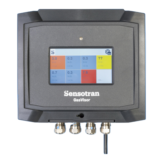
1. INTRODUCTION The GasVisor is a gas detection control panel with 3 alarm levels and a fault relay with independent potential-free contact. Optionally, you can add a ModBus relay expansion module, or a connectivity card that can include Ethernet output connection, 4 Modbus RS485 input channels, LoRA modem or NB-IoT LTE modem. -
Page 5: Specifications
Display 4.7" TFT with 480 x 272 resolution User Interface Capacitive Touch Screen Temperature -20 to 60ºC Humidity 0 – 95% RH (non condensing) Pressure 0.9 – 1.1 Atm Relay Contacts 250 V, 2 A normally open V2.0 Sensotran, s.l – 19/04/2024 Page 3... -
Page 6: Operation
2. OPERATION Prior to shipment, each GasVisor has been verified. However, the user should check the operation before the first use. Once the unit has been installed, it must be checked for proper operation. Physical Description Installation Connect the power between 110 and 230 VAC / 50-60 Hz, at the JP2 connector as shown in Figure 1. - Page 7 S8. Channels S5, S6, S7 and S8 are optional depending on the configuration purchased. The outputs of the alarm relays will be connected to A1 for Alarm 1, A2 for Alarm 2, A3 for Alarm 3 and FA for the Fault relay. FUSIBLE F9 Figure 1 V2.0 Sensotran, s.l – 19/04/2024 Page 5...
-
Page 8: General Operation Of The System
Analog sensor 5 (4-20 mA) 3. GENERAL OPERATION OF THE SYSTEM When the GasVisor alarm control panel is switched on, the system load the program and verify all parameters for approximately 1 minute. After this time, the system will be on operation. -
Page 9: User Interface
(in groups of 16). access the settings menu. silence the buzzer in the event of an alarm. The different states of the configured sensors are displayed next to the channel number with a colored box, and can be: V2.0 Sensotran, s.l – 19/04/2024 Page 7... -
Page 10: System Configuration Menu
Then enter the access code 1250 and press the Accept button. If the code entered is correct, you will be taken to the menu. If it is incorrect, it will return to normal operating mode. Accept Cancel V2.0 Sensotran, s.l – 19/04/2024 Page 8... -
Page 11: Channel Configuration
Channel Configuration In the menu, you can configure different parameters that affect the operation of each channel: Select channel to configure Turn the channel On and Off. Channel configuration. Gas configuration. Alarm configuration. Remote relay configuration (optional). V2.0 Sensotran, s.l – 19/04/2024 Page 9... - Page 12 Configure the gas type of the selected channel. The numbers correspond to the three central numbers of the references of the Sensotran devices, automatically configuring the ranges and alarms with the corresponding ones of the corresponding Sensotox, iSens or Sensotox C2.
-
Page 13: General Operation Of Alarms
GENERAL OPERATION OF ALARMS The GasVisor control unit has 4 relays that are used to activate 4 different alarms. The first three are used as normal alarms and the fourth as a fault alarm. If the alarm for any channel is triggered, it will be displayed in a different color, depending on the alarm that has been triggered, and a bell will appear in the channel box. - Page 14 10 ppm and a hysteresis of 2 ppm, the alarm will be triggered at 10 ppm and deactivated below 8 ppm. - Delay: Sets the delay in triggering relays in the event of an alarm in seconds. V2.0 Sensotran, s.l – 19/04/2024 Page 12...
- Page 15 Rev. Description of Changes Date Initial Release 01/02/2023 Menu Description Update 19/04/2024 V2.0 Sensotran, s.l – 19/04/2024 Page 13...
- Page 16 Bergueda 1 Floor 2 Office A3 Mas Blau Industrial Estate El Prat de Llobregat BARCELONA – SPAIN Tel. +34 93 478 5842 sensotran@sensotran.com V2.0 Sensotran, s.l – 19/04/2024 Page 14...
Need help?
Do you have a question about the GasVisor and is the answer not in the manual?
Questions and answers