
Subscribe to Our Youtube Channel
Summary of Contents for STORK TRONIC Commander Touch 4
- Page 1 Commander Touch 4 User manual Order no. 900334.003 As of: March 2024 Order number: 900334.003 Page 1...
-
Page 2: Table Of Contents
Content Safety instructions ..............................4 Intended use ..............................4 Operating conditions ............................4 Regular checks ..............................4 Technical requirements ............................. 5 Hardware requirements ............................ 5 Software requirements for the cloud ........................ 5 Network requirements ............................5 General information..............................6 Description ................................ 6 Specifications .............................. - Page 3 6.5.3 Naming ................................ 27 6.5.4 Add ................................28 6.5.5 Remove ............................... 29 6.5.6 Info ................................30 E-mail configuration ............................31 6.6.1 Address book .............................. 31 6.6.2 E-mail server ............................... 32 Alarm management ............................33 Functions ................................. 35 6.8.1 Scenes ................................. 35 USB ..................................
-
Page 4: Safety Instructions
1 Safety instructions Electrostatic sensitive device Do not reach into the circuit or into the plug connectors Ensure potential equalization before working on the device Only plug in the plug when it is de-energized Plugging in live leads to contact wear and malfunction 1.1 Intended use Installation, connection and commissioning may only be carried out by a qualified electrician. -
Page 5: Technical Requirements
2 Technical requirements The necessary network infrastructure in the form of hardware, software and services for the proper functioning of the Commander Touch 4 (in short: device) is described below. 2.1 Hardware requirements You should have a stable and fast Internet connection. Preferably via DSL or better fiber optics, in which case you will... -
Page 6: General Information
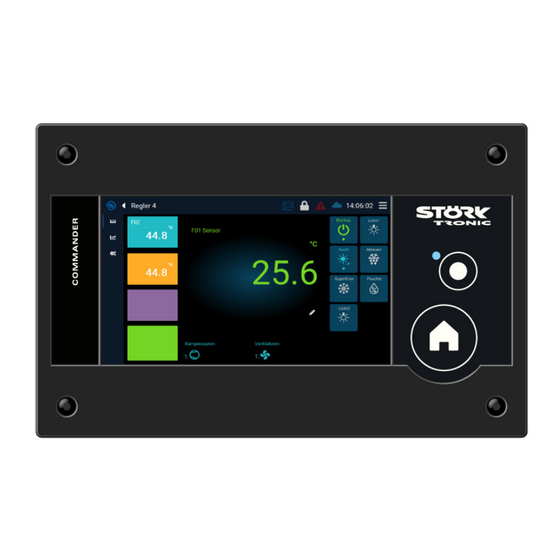
3 General information 3.1 Description The new Commander Touch 4 enables remote maintenance and remote control of networked controller systems. It has a high-resolution, capacitive 4.3" touchscreen with 800x480 pixels. All inputs can be made directly and intuitively via the display. -
Page 7: Operation
3.3 Operation The Commander is operated by directly tapping the respective buttons or symbols on the touchscreen and/or using the additional operating buttons. Button: HOME Pressing the HOME button always takes you to the start screen with an overview of all configured controls. -
Page 8: Main Screen
4 Main screen 4.1 Controller list After starting or pressing the HOME button, the main screen with the controller list is displayed. The controller list provides a complete overview of all configured controllers connected to the Commander, including the main measured value transmitted by them. You can choose between a 4-column layout and an automatic arrangement, see chapter 6.10.4 The controllers are shown in different colours in this overview. -
Page 9: Controller Details
5 Controller details If you click on the tile of a controller on the overview page, you will be taken to its details page. Different types of controllers can be connected to the Commander. A separate overview is displayed for each controller type. -
Page 10: Setpoint Adjustment
5.1 Setpoint adjustment To change the main setpoint, tap directly on the corresponding icon in the overview In the dialogue that opens, the setpoint can be changed within the setpoint limits. To do this, drag the slider to the desired temperature or change the value using the + / - buttons. Alternatively, tapping directly on the current value and entering the new value using the on-screen keyboard. -
Page 11: Chart
5.2 Chart Tapping on the corresponding symbol opens the chart overview. The chronological sequence of all measured values of the selected controller is displayed here. The chart can be scrolled and zoomed using touch gestures. Tapping on the arrow symbol jumps back to the current time. Predefined time periods can be selected by tapping on these symbols: Order number: 900334.003 Page 11... -
Page 12: History
5.3 History The event history of the Commander or a connected controller can be called up here. To do this, first select the desired unit. The event history is displayed. Tapping on the alarm icon displays the last alarm events. Order number: 900334.003 Page 12... -
Page 13: Menu
6 Menu The menu opens by tapping on the corresponding icon in the status bar 6.1 Settings The basic properties of the Commander can be defined in the settings. Order number: 900334.003 Page 13... -
Page 14: Language
6.1.1 Language Tap the button for the desired language. The selected language is adopted immediately and the main screen appears. 6.1.2 Temperature unit Select the desired temperature unit and confirm the selection. Order number: 900334.003 Page 14... -
Page 15: Date And Time
6.1.3 Date and time Tap the button for the day, month, hour, minute and second in succession. The dialogue box for setting the respective value appears. Tap on the "Time zones" button and first select the continent and then the region. Confirm with the "Save"... -
Page 16: Recording
6.1.5 Recording The recording interval is the time interval between two measuring points. It can be freely selected in the range between 10 and 1500 seconds (25 min.). The setting applies to all connected controllers. The factory setting is 120 seconds, which is sufficient for a 12-month recording. -
Page 17: Master Address
6.1.6 Master address The ST bus address of the Commander can be changed here. This is only necessary if several commanders (masters) are to be used in the same network. In this case, they must be assigned different addresses. It is recommended to only use addresses > 247. 6.2 Information Here you can call up various information about the device. -
Page 18: User Management
6.3 User management Users can be created and deleted in the user management. In addition, rights for different user roles can be defined and assigned to one or more users. 6.3.1 User After selecting the " User" menu item, a list of the currently available users is displayed. By default, there is only the user "ADMIN"... -
Page 19: Rights
To change the profile of a user, tap the "Profile" button for the user whose profile is to be changed. The screen for assigning the profile to the user appears. Tap the option field for the respective profile and tap Save. 6.3.2 Rights The user profiles are managed here. -
Page 20: Auto-Logout
Tap on the "Left" and "Right" buttons to display the rights for the various profiles. Tap on the sliders to assign the individual rights for "Show" and "Change". If you want to exit the screen page without saving: Tap on "Cancel Setpoints: Displaying and changing setpoints Parameters: Display and change parameters... -
Page 21: Remote Access
6.4 Remote access The Commander can be integrated into a local network. To do this, the IP address, subnet mask and the default gateway (usually the IP address of the router) must be specified. 6.4.1 IP configuration Either select "DHCP" or specify the IP address, subnet mask and default gateway manually. 6.4.2 DNS configuration Specify the desired DNS server. -
Page 22: Cloud Configuration
6.4.3 Cloud configuration In this dialogue, the "CloudConnect ID" can be read out and the controller can be connected to the cloud. In the initial state, the Commander is not connected to the cloud. Tap this button to establish a connection to the cloud. The Commander attempts to establish the connection: Order number: 900334.003 Page 22... - Page 23 A successful connection is indicated by a green checkmark in the status bar. In addition, the individual 13-digit CloudConnect ID of the Commander can now be read out. Disconnects the connection to the cloud Meaning of the different CloudConnect status icons in the status bar: No symbol: Commander is not online The Commander is online, but there is no connection to the cloud...
-
Page 24: Network Test
6.4.4 Network test Carry out a network test to check your settings. Order number: 900334.003 Page 24... -
Page 25: Controller
6.5 Controller The functions and settings available here can be called up individually for each connected controller. To do this, first select the desired controller after each menu item. 6.5.1 Parameter Each controller can be parameterised remotely from the Commander. After selecting the controller, the desired parameter level can be selected. - Page 26 For a better overview, the currently selected controller is always displayed in the top menu bar. The parameter to be changed is selected. The parameter name, the current value and the setting limits are displayed in the parameter overview. The value can be changed within the limits using the +/- symbols or the slider.
-
Page 27: Actual Values
6.5.2 Actual values All actual values of the selected controller are listed. The meaning of the individual measured values can be found in the documentation for the respective controller. 6.5.3 Naming You can rename a controller here. Order number: 900334.003 Page 27... -
Page 28: Add
6.5.4 Add After calling up the "Add" function, the Commander searches for the connected controllers and offers the option of naming them. If controllers have already been configured, they are also listed with any names that have already been assigned. NOTE: An individual ST bus address must be set for each controller in the network using parameter L0. -
Page 29: Remove
After a successful search, a list of all controllers found and their addresses is displayed. 6.5.5 Remove If a controller is to be removed from the network, first delete it from the system here. Attention: All recorded data for this controller will be irretrievably deleted! Order number: 900334.003 Page 29... -
Page 30: Info
6.5.6 Info The information on the software of the connected controller is displayed: Order number: 900334.003 Page 30... -
Page 31: E-Mail Configuration
6.6 E-mail configuration The Commander also offers the option of sending alarms by e-mail. Various e-mail addresses and an e-mail server can be configured for this purpose. 6.6.1 Address book Here you can collect the addresses that are to be used in the alarm configuration. The "New"... -
Page 32: E-Mail Server
A name and a comment can also be stored for each e-mail address. 6.6.2 E-mail server Enter the data for the e-mail server here: "Name": Assign a name for the server. "User name": User login to e-mail server (smtp) "User password": Associated password "Sender": Appears in the e-mail as the e-mail address of the sender... -
Page 33: Alarm Management
6.7 Alarm management IYou can define three different e-mail alarms in alarm management: Warnings • Alarm with medium priority ("Alarm 1") • Alarm with high priority ("Alarm 2") • Various e-mail recipients and alarm events can be defined for each alarm. The alarm functions of the relay and the buzzer are also configured here Example for a new Alarm 1: Order number: 900334.003... - Page 34 The alarms are defined using the "Add" button. First, the controllers to be analysed are determined on the left and then the alarm criteria are defined on the right. Various alarm messages can be activated for the alarm: - Sensor break - Sensor short circuit - Temperature alarm (maximum) - Temperature alarm (minimum)
-
Page 35: Functions
6.8 Functions Various functions (so-called scenes) can be created and edited here. These are either executed automatically at certain times or are then available as a "scene" on the main screen. 6.8.1 Scenes A scene is created by first selecting the desired controller at the bottom left. Next, you can specify whether the scene is activated time-controlled (time/day of the week) or manually ("Immediately"). - Page 36 Manual functions can be triggered using the corresponding buttons in the "Scenes" section in the title bar of the Commander. Order number: 900334.003 Page 36...
-
Page 37: Usb
6.9 USB A USB stick can be plugged into the back of the Commander to perform various functions. 6.9.1 Export History Press the "Export history" button. Insert the USB stick and select "OK". All recorded data is then copied to a USB stick. A directory is automatically created and the exported data is stored in it. -
Page 38: Export Configuration
6.9.2 Export configuration Tap on the "Export configuration" symbol and proceed in the same way as for data export. 6.9.3 Import Tap on "Import" to import a previously exported configuration. The existing configuration on the data storage device is displayed. Order number: 900334.003 Page 38... -
Page 39: Service
6.10 Service Various maintenance and view options can be set in the Service area. 6.10.1 Battery A maintenance interval for the integrated battery can be read off here. By tapping the button, the interval can be set between 0 and 120 months. Order number: 900334.003 Page 39... -
Page 40: Reset Interval
6.10.2 Reset interval The maintenance interval for the battery can be reset by tapping this button. It is then restarted from the beginning. 6.10.3 Factory reset A system reset of the Commander can be carried out here, which resets it to the factory settings. The following settings are reset: Timer configuration •... -
Page 41: Overview
6.10.4 Overview This defines the style of the controller list, which can be called up using the "Home" button. 6.10.5 Commander Outputs Here you can activate or deactivate the buzzer and the alarm relay. 6.10.6 Menu style This allows you to switch between the "Tile" and "List" variants of the menu. Order number: 900334.003 Page 41... -
Page 42: Technical Data
7 Technical data Display TFT colour screen, 800 x 480 pixels, 4.3" diagonal LED backlight, dimmable brightness. Capacitive touchscreen Power supply 12-24V DC Connectors USB type A, shielded, host RJ45 8-pin, shielded, ETHERNET 2x RJ45, shielded, ST-Bus 1 plug-in terminal (3-pin) for ST bus 1 1 plug-in terminal (7-pin) for relay, switching input and power supply Environmental conditions Storage temperature... -
Page 43: Wiring Diagram
7.1 Wiring diagram 7.2 Dimensions Installation data The device is designed for installation in a control panel. Front dimensions 166 mm x 106mm Panel cut-out 157 mm x 97mm (observe drawing) Order number: 900334.003 Page 43...
Need help?
Do you have a question about the Commander Touch 4 and is the answer not in the manual?
Questions and answers