
Summary of Contents for Hoefer VP200
- Page 1 VP200 Vacuum Pump For use with the Hoefer GD2000 Vacuum Gel Dryer VP200-IM...
-
Page 2: Table Of Contents
Page Finder Important Information ..........ii Waste Electrical & Electronic Equipment (WEEE) ..vii 1. VP200 Vacuum Pump function and description ...1 2. Specifications ...........3 3. Important information ........4 4. Operating instructions ........5 5. Troubleshooting ..........9 6. Care and maintenance ........10 7. -
Page 3: Important Information
Important Information – English použity pouze řádně vyškolený operátorů. Číst celé toto ruční před použitím nástroje a použití pouze v • If this equipment is used in a manner not specified by souladu s pokyny. Hoefer, Inc. the protection provided by the equipment • Přístroj musí být vždy používají se na výkonu zemi vést may be impaired. šňůra správně zemněny k zemi na síti výústce. • This instrument is designed for indoor laboratory • Využití pouze nepoškozené elektrické dráty a vybavení use only. pro napětí budete používat. Všechna zařízení spojené • Only accessories and parts approved or supplied by s vysokým napětím by měla být v souladu s EN61010- Hoefer, Inc. may be used for operating, maintaining, 1:2001. and servicing this product. • Si ponechá nástroje jako suchý a čistý jako možné. • Warning! Because this instrument can develop suffi- Otřete pravidelně s a měkké, vlhkým hadříkem. Nechť cient voltage and current to produce a lethal shock, je nástroj nenastavený úplně před použitím. care must be exercised in its operation. • Nejsou provozována na nástroj v extrémní vlhkost (nad • This instrument is designed in accordance with the 80%). Předešlo kondenzaci o pronájmu jednotky na EN61010-1:2001 electrical safety standard. Never- okolní teplotu nechá při přijímání nástroj z chladnější... - Page 4 • Tämä väline suunnitellaan sisälaboratoriokäytölle vain. • At tillade tilstrækkelig afkøling, forsikrer, at lufthullerne • Vain lisävarusteet ja osat hyväksyivät tai toimitti af instrumentet er ikke dækket. Hoeferin oheen, Inc.:ää voi käyttää käyttämiselle, valvoalle, ja servicing tämä tuote. Belangrijke Informatie – Dutch • Varoittaminen! Koska tämä väline voi kehittää riittävä jännitteen ja virran tuottaa kuolettavan järkytyksen, • Indien deze uitrusting in een manier wordt gebruikt huolta täytyy harjoittaa toiminnossaan. die niet door Hoefer is gespecificeerd, Nv. de • Tämä väline suunnitellaan EN61010-1:2001 sähkö- bescherming die door de uitrusting is verzorgd kan turvallisuusstandardin mukaisesti. Silti pitäisi käyt- worden geschaad. tää vain ohi oikeasti koulutetut käyttäjät. Lue tämä • Dit instrument is voor binnenlaboratoriumgebruik kokonainen manuaalinen ennen välinettä ja käyttö enkel ontworpen. vain ohjeiden mukaan. • Enkel onderdelen en delen keurden goed of leverden • Välinettä täytyy käyttää aina valtanuoran maalyijystä door Hoefer, Nv. kan voor het bedienen worden perusti oikein maadoittaa sähköverkkoaukossa. gebruikt, handhavend en onderhouden van dit • Käyttää vain undamaged sähkömetallilankaa ja varus- product.
- Page 5 • Garder l’instrument aussi sec et propre comme possi- ble. Essuyer régulièrement avec un doux, étouffer du • Um das genügend Abkühlen zu erlauben, stellen Sie tissu. Laisser l’instrument sèche complètement avant sicher, dass die Öffnungen des Instrumentes nicht l’usage. bedeckt werden. • Ne pas fonctionner l’instrument dans l’extrême Informazioni Importanti – Italiano humidité (au-dessus de 80%). Eviter la condensa- tion en laissant l’equilibrate d’unité à la température • Se quest’apparecchiatura è usata in un modo ambiante en prenant l’instrument d’un plus froid à un specificato da Hoefer, Inc. la protezione fornito environnement plus chaud. dall’apparecchiatura potrebbe essere indebolita. • Permettre le refroidissement suffisant, garantir que les • Questo strumento è disegnato per l’uso di laboratorio conduits de l’instrument ne sont pas couverts. interno solo. • Solo gli accessori e le parti hanno approvato o hanno Wichtige Informationen – German fornito da Hoefer, Inc. potrebbe essere usato per oper- • Wenn diese Ausrüstung gewissermaßen nicht angege- are, per mantenere, e per revisionare questo prodotto. ben durch Hoefer, Inc verwendet wird, kann der • Avvertendo! Perché questo strumento può sviluppare...
- Page 6 Viktig Informasjon – Norwegian • Ten instrument został zaprojektowany zgodnie z tym EN61010-1: 2001 Bezpieczeństwo elektryczne • Hvis dette utstyret blir brukt i en måte ikke spesifisert standard. Niemniej jednak, należy stosować jedynie ved Hoefer, Inc. beskyttelsen som ha blitt git av utsty- przez odpowiednio przeszkoleni operatorów. Znajdą ret kan bli svekket. państwo to cały podręcznika przed zastosowaniem instrumentu i stosować jedynie zgodnie z instrukcjami. • Dette instrumentet er utformet for innendørs labora- toriumbruk bare. • Instrument musi zawsze być wykorzystane z ziemi doprowadzić do zasilania detonującego właściwie • Bare tilbehør og deler godkjente eller forsynte ved uzasadnione na ziemię w sieci wodociągowej Hoefer, Inc. kan bli brukt for drive, vedlikeholde, og rynku zbytu. betjene dette produktet. • Wykorzystanie tylko nieuszkodzona elektrycznych • Varsler ! Fordi dette instrumentet kan utvikle tilstrek- drutów i urządzenia specjalne do napięć zapłacą kelig spenning og strøm til å produsere et dødelig wykorzystania. Wszystkie urządzenia podłączone do sjokk, må bli øvd bekymring i dets drift. wysokiego napięcia powinny być zgodne z EN61010-1: • Dette instrumentet er utformet i samsvar med 2001. EN61010-1:2001 elektrisk sikkerhetsstandard. Likevel • Kontrolować instrumentu jako suche i czyste jak to...
- Page 7 • Usa fio eléctrico só intacto e equipamento específico instrumento de un más frío a un ambiente más tibio. para as voltagens que você usará. Todo equipamento conectado a voltagem alta deve ser de acordo com • Permitir refrigeración suficiente, asegure que las EN61010-1:2001. aberturas del • Mantem o instrumento tão seco e limpo como Viktig Information – Swedish possível. Limpe regularmente com um pano húmido macio. Deixe o instrumento secar completamente • om denna utrustning används i ett sätt som inte har antes de uso. specificeras av Hoefer, Inc. skyddet tillhandahöll vid • Não opera o instrumento em humidade extrema utrustningen kan skadas. (acima de 80%). Evite condensação deixando o equili- • Detta instrument formges för inomhuslaboratorium brate de unidade a temperatura ambiental quando användning bara. tomar o instrumento de um mais frio a um ambiente • Bara medhjälpare och delar godkände eller levererade mais quente. vid Hoefer, Inc. kan användas för fungera, underhålla, • Permitir esfriar suficiente, assegura que as aberturas do och servicing denna produkt. instrumento não são cobertas. • varna! Därför att detta instrument kan utveckla tillräck- lig spänning och ström att producera en dödlig stöt,...
-
Page 8: Waste Electrical & Electronic Equipment (Weee)
Waste Electrical and Electronic Equipment (WEEE) English This symbol indicates that the waste of electrical and electronic equipment must not be disposed as unsorted municipal waste and must be collected separately. Please contact an authorized representative of the manufacturer for information concerning the decommissioning of your equipment. -
Page 9: Vp200 Vacuum Pump Function And Description
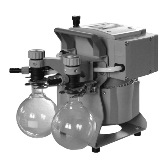
1. VP200 Vacuum Pump function and description The VP200 Vacuum Pump is especially well suited to dry gels on the Hoefer GD2000 Vacuum Gel Dryer — the pump is highly resistant to water vapor, acid, and gel staining Important! Remove both protective port covers before solution vapors. - Page 10 If any part is missing, contact your local Hoefer, Inc. sales office. Inspect all components for damage that may have occurred while the unit was in transit. If any part appears damaged, contact the carrier immediately.
-
Page 11: Specifications
1.2/1.4 cfm when it is: Ultimate (total) pressure 7/5 mbar/torr • used in laboratory locations. (absolute) • used as delivered from Hoefer, Ultimate (total) pressure 12/9 mbar/torr Inc. except for alterations (absolute) with gas ballast described in the user manual. -
Page 12: Important Information
• Always disconnect the power cord before servicing. • If using the VP200 pump with instruments other than the Hoefer GD2000 Gel Dryer, ensure that the vacuum pressure rating is suitable for the application and that the pumped gases are compatible with the materials listed on page 7. -
Page 13: Operating Instructions
4. Operating instructions Setting up the GD2000 system Connecting the VP200 vacuum pump to the Hoefer GD2000 Vacuum Gel Dryer. Use the mounted handle when moving the pump. Important! Remove both red protective coverings from the inlet and outlet ports, if they are in place. - Page 14 Installing a cold trap You may install a cold trap, such as a vacuum flask in dry ice, between the gel dryer and the pump. A cold trap is not required to protect the pump, but it minimizes the amount of vapor released to the atmosphere.
- Page 15 The VP200 Vacuum pump as a component in other systems The VP200 Vacuum Pump can be used for any application in which the requirements are within the stated pump ratings (see pump specifications, page 3) and in which the pumped gases are...
- Page 16 If you will be evacuating a system containing hazardous vapors: • Adopt suitable measures to prevent the release of Note: The pump’s residual dangerous, explosive, corrosive or polluting fluids leak rate is extremely low, but from the pump outlet. Always install the catchpots an exchange of gas between the environment and the at the outlet port and if required, install a suitable...
-
Page 17: Troubleshooting
Clear any blockage at the outlet end of the system. If the pump seizes, call your local Hoefer, Inc. sales office. Pump does not achieve Close the gas ballast valve (arrow pointing up or down rated pressure or normal... -
Page 18: Care And Maintenance
6. Care and maintenance All bearings are sealed and filled with non- wearing lubricant. Under normal operating conditions, these components require no maintenance. Serviceable parts include the catchpots, diaphragms, and valves. Their care is described below. Adjusting the gas ballast valve When the gas ballast valve is in the open position (Fig 2, page 7), a small amount of air enters the system through a pinhole at the bottom of the... - Page 19 Pump head components K. Square nut (not shown) A. Head alignment pin/mark (not shown) B. Connecting rod L. Fillister head screw (not shown) M. O-ring C. Housing N. Valve D. Washer O. Valve head E. Diaphragm support disc F. Diaphragm P.
- Page 20 Servicing diaphragms and valves If your pump no longer achieves the rated Note: Under normal wear, vacuum, possible causes include an accumulation diaphragms and valves should perform satisfactorily for a of condensates inside the pump head or damage minimum of 10,000 operating to sealing parts.
- Page 21 Pump on pump support: Remove catchpots at inlet and outlet. Remove the 4 screws affixing the head cover cowling (W) with a Torx driver T20. Pay attention to the washers under the screws and remove. Pull of head cover cowling (W) carefully. Do not tilt. Step 3 Pump at pump support: Detach the coupling of the connection tube (V) to the...
- Page 22 Replacing the diaphragm Disassemble head covers (J) to check the diaphragm (F). Unscrew four (pump with one/two heads) Allen screws (H) with a 5 mm wide Allen key. Remove both head covers (J) together with valve heads (O) and connections. Step 1 Check diaphragm (F) for damage and replace if necessary.
- Page 23 Position new diaphragm (F) between diaphragm clamping disc with square head screw (G) and diaphragm support disc (E). Note: Position diaphragm with pale side towards diaphragm clamping disc (facing pump chamber). Make sure that the square head screw of the diaphragm clamping disc is correctly seated in the guide hole of the diaphragm support disc.
- Page 24 Replacing the valves Open the hinged cover of the connection fastener (Q) with a slotted screwdriver. Loosen connection fastener slightly. Turn the fillister head screw (L, not shown) with a Torx driver T20 at most one turn. Do not detach the fillister head screw from the square Step 1 nut (K, not shown).
- Page 25 Remove valve heads (O) along with the disc springs (R), connection tube if applicable, hose nozzles (P) and connection fasteners (Q) or move the valve heads carefully aside. Note position and orientation of the valve heads. Note position and alignment of valves (N). Check valves (N) and O-rings (M) for damage and soiling.
- Page 26 Valve head with gas ballast or hose nozzle connection: Insert square nut (K, not shown) in the groove of the head cover (J) or position square nut in the groove and then screw on connection fastener. Loosely fasten fillister head screw (L, not shown). Position clamping bracket (S) with countersunk bores facing upwards.
- Page 27 Reassembly Pump on pump support: Affix the connection tube (V) to the other side of the pump, as well as the hose connection to the inlet or outlet of the vacuum system at the valve head (O). Step 1 Slip connecting tube (V) onto hose connection of valve head.
- Page 28 Checking the ultimate vacuum After any intervention at the equipment (e.g., repair/ maintenance) the ultimate vacuum of the pump has to be checked. Only if the pump achieves its specified ultimate vacuum, the pump’s leak rate is low enough to ensure that no explosive atmospheres will occur in the interior of the equipment.
-
Page 29: Ordering Information
VP200RK-7 Diaphragm VP200RK-8 Companion products Hoefer GD2000 Vacuum Gel Dryer System Includes: VP200 Vacuum Pump, and vacuum tubing, stainless steel screen, 10 sheets of filter paper, 50 sheets of porous cellophane, mylar sheet and porous polyethylene sheet. 115 V~ GD2000-115V... - Page 30 Hoefer, Inc. 32 Scotland Blvd, Ste. 9, Bridgewater, MA02324, USA Toll Free: 1-800-813-0488 Phone:1-508-807-4665 E-mail: support@hoeferinc.com Web: www.hoeferinc.com Hoefer is a registered trademark of Hoefer, Inc. © 2023 Hoefer, Inc. — All rights reserved.
Need help?
Do you have a question about the VP200 and is the answer not in the manual?
Questions and answers