Table of Contents
Advertisement
Quick Links
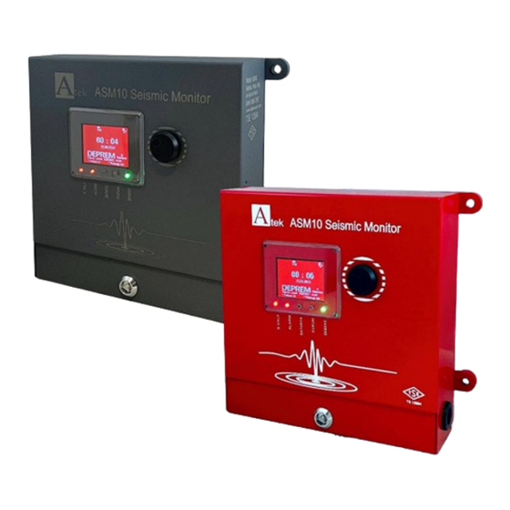
SEISMIC EARTHQUAKE PANEL
• Shaking detection in 3 axes
• Automatic offset feature
• Keeping the last 100 earthquake events in memory and
viewing them from the menu
• Up to 24 hours of operation with internal battery for
situations such as power outages
• Color LCD display and status LEDs
• Audible and visual warning in case of earthquake or error
• 4 pcs dry contact relays (2 standard, 2 optional) and 1 pcs
12V 5A solenoid output that can be set in different functions
• 7 language options
• Sturdy and durable structure
• Easy installation
ASM 10
USER
MANUAL
Advertisement
Table of Contents

Summary of Contents for Atek ASM 10
- Page 1 ASM 10 SEISMIC EARTHQUAKE PANEL • Shaking detection in 3 axes • Automatic offset feature • Keeping the last 100 earthquake events in memory and viewing them from the menu • Up to 24 hours of operation with internal battery for...
-
Page 2: Table Of Contents
9.4.8 FREQUENCY MEASUREMENT MENU..…………………………………………………….…….……. 21 9.4.9 TEST MENU…..……………..……………………………………………………………….……..…….….…. 21 BOX CONTENTS Product Description ASM 10 Seismic Earthquake Panel 1 pcs User Manual 1 pcs Ø10x45 Plastic Dowel 4 pcs DIN7981C 6.3x60 Screw 4 pcs Connection Terminal 4 pcs triples, 1 pcs dual Panel Key 1 pcs KK-ASM.001 05.12.23 REV NO:2... -
Page 3: General Informations
ENERAL NFORMATIONS ASM 10 Seismic Earthquake Panels have very sensitive sensors that can detect seismic movements in three axes (x,y,z,). It detects the seismic vibrations that occur during an earthquake and gives control output and it is designed to automatically disable the devices such as gas valves, generators, electrical panels, elevators, etc. -
Page 4: Warnings
2. W ARNINGS IMPORTANT NOTE (!): BEFORE OPERATING THE DEVICE, MAKE SURE TO READ THE "ASM-10 EARTHQUAKE SENSOR COMMISSIONING GUIDE" PROVIDED WITH THE DEVICE AND FOLLOW THE STEPS SPECIFIED IN THE GUIDE. 1) The connection must be made by authorized personnel, taking into account the safety warnings. 2) Installation of the device;... -
Page 5: Technical Features
3. T ECHNICAL EATURES • Operating Voltage 85-305 VAC, 47-440 Hz Quiescent Current 19mA @230 VAC Power Drawn 4,37W @230 VAC (typical) 14V (+/-0.2V) Battery Charging Voltage Battery Charging Current 500mA max. From 12V Battery (While %100 full): While the device is in stand-by state: 20mA Current Drawn from the The device is in normal operating state, there is no alarm: 48mA Battery... -
Page 6: Installation
4. I NSTALLATION 4.1 Mechanical Dimensions 4.2 Mechanical Mounting Selection of Mounting Location 1) A closed area (inside the building) and the closest distance to the Solenoid valve or application location should be selected for installation. 2) In order to detect the intensity of the earthquake, it must be mounted on a solid area such as a column or beam. -
Page 7: Electrical Connections
4.3 Electrical Connections SAMPLE CONNECTION DIAGRAMS KK-ASM.001 05.12.23 REV NO:2... -
Page 8: Test And Control
1) Connections must be made in accordance with the instructions in the user manual. 2) In order to avoid damage to the product, the supply voltage and other technical data specified in the user manual should be taken into consideration and energy should not be applied before all connections are made. -
Page 9: Button Functions
6. B UTTON UNCTIONS There is 1 rotary button on the device. Access and control of menus is provided by this button. Press the button Rotate Right Rotate Left If pressed and released once; Navigating through menus; Navigating through menus; Entering or confirming the menu forward back... -
Page 10: Warning Conditions
8. W ARNING ONDITIONS Alarm or Error Message Explanation During an earthquake, an alarm message as shown on the left appears on the device screen. Also the buzzer sounds (buzzer output graph is given below). Solenoid output becomes active. If the relevant function is assigned, Relay outputs are also active. The device cannot be reset unless it reaches the offset position. -
Page 11: Menu Operations And Programming
9. M PERATIONS AND ROGRAMMING 9.1 Entering The Menu When the device is in normal operating state, press and release button once. In this case, the device will ask for a password and the password screen will appear as below. The cursor automatically moves to the first digit. -
Page 12: Menu List
9.3 Menu List MENU Explanation Options From this menu; • Device version information can be displayed, • With the RESET operation, the device can be reset in cases such as device offset adjustment or sensor error. • With the language menu, any of 7 language options (Turkish, English, German, Spanish, Portuguese, Italian, Dutch) can be selected. -
Page 13: Detailed Menu Descriptions
MENU Explanation Earthquake Record The earthquake log menu keeps a log of the last 100 earthquake events and the last 200 light shaking events (set for relay output) detected by the device. The last event is shown first. Along with date and time information, it also shows the shaking intensity on the X, Y and Z axes. -
Page 14: Acceleration Measurement Menu
➢ Language: The device has 7 language options: Turkish, English, German, Spanish, Portuguese, Italian and Dutch. For language selection; After entering the menu, turn the button to the right or left and move to the "LANGUAGE" tab with the red cursor. The button is pressed once. In this case, the cursor will be green. -
Page 15: Output Control Menu
9.4.3. Output Control Menu This is the menu where solenoid (error notification, activation status), relay (slight shaking threshold, activation status) and buzzer (shaking threshold, warning duration, output test) settings are made. Additionally, earthquake alarm resetting can be done from this menu. After entering the menu, turn the button to the right or left to move the red cursor to the... - Page 16 Solenoid : The solenoid output is activated according to the selected output type. Severe shaking can be selected as lock, severe shaking as sld, severe shaking as signal. Output types and function descriptions are shown in the table on page 15. Note: In case of an earthquake, the solenoid output becomes passive after being active for 5 mins.
- Page 17 When a slight shaking occurs, the relay output gives continuous output. Slight Shake Lock (Relay1, Relay2, Relay3, Relay4) When a slight shaking occurs, the relay output gives an output every 10 seconds. Slight Shake Sld (Relay1, Relay2, Relay3, Relay4) When a slight shaking occurs, the relay output gives an output every second.
- Page 18 When an intense shaking occurs, the solenoid or relay output gives an output every 10 seconds. In this mode, the solenoid pulls a maximum of 250 times. Intense Shake Sld (Relay1, Relay2, Relay3, Relay4, Solenoid) When an intense shaking occurs, the solenoid or relay output gives an output every second.
-
Page 19: Battery Status Menu
9.4.4. Battery Status Menu Battery voltage and battery charge percentage information are displayed. Additionally, the low battery limit and charging type can be adjusted from this menu. With the battery "enabled/disabled" mode, the device can be prevented from giving an earthquake warning by disabling the battery in situations such as transporting the device. -
Page 20: Display Settings Menu
By turning the button to the right or left again, the parameter value is increased / decreased or the optional parameters are switched. After the desired value is entered or selected, the button is pressed once to save the selection and the cursor turns red. -
Page 21: Earthquake Record Menu
Test Mode It can be selected as Yes or No. It is set to "Yes" to speed up the tests to be carried out in the factory and TSE. It should be selected as “No” during normal use. 9.4.7 Earthquake Record Menu The earthquake log menu keeps track of the last 100 earthquake events detected by the device. -
Page 22: Frequency Measurement Menu
9.4.7.2. Earthquake List Menu This is the menu which earthquake logs are displayed in list form. The last 100 earthquake events can be viewed. The last earthquake event is shown first. After entering the menu, you can switch between pages by turning the button to the right or left. - Page 23 Testable Inputs or Outputs Encoder It is used to check whether the encoder is working or not. It can be tested between -10 and +10. Buzzer, Relay1, Relay2, Relay3, Relay4, Selonoid Relays are used to check whether the solenoid and buzzer are working properly. Outputs can be active with “0N”...
- Page 24 ALFA ELEKTRONİK SENSÖR SANAYİ VE TİCARET A.Ş. Gebze OSB, 800. Sokak, No:814, Gebze/KOCAELİ/TÜRKİYE Tel : +90 (262) 673 76 00 Fax : +90 (262) 673 76 08 Web : www.alfasanayi.com KK-ASM.001 05.12.23 REV NO:2...
Need help?
Do you have a question about the ASM 10 and is the answer not in the manual?
Questions and answers