Advertisement
SERVICE MANUAL
English
B3
Deutsch
Francais
SE
vg
a
SPECIFICATIONS
FM SECTION
Frequency range
Usable
sensitivity
90 dB quieting sensitivity
Signal-to-noise ratio (at 66 dBf)
Total harmonic distortion (at 6 dBf)
00 Hz
TkHz
6 kHz
Frequency response
Image response ratio
Spurious response ratio
iF response ratio
Selectivity
Capture ratio
AM
suppression
Stereo separation
Subcarrier
suppression
SCA rejection
Muting threshold
Antenna input
AM SECTION
Frequency range
Sensitivity
Image rejection
Selectivity
Signal-to-noise ratio {at 50 mV)
Antenna
AUDIO SECTION
Output
RMS Power
{Both channels driven)
FEATURES
88 —
108 MHz
Mono:
1.0 pV (75 ohms, IHF and DIN)
Stereo
20 dBf (5 S5yV)(
) ts indicateed IHF 58
10 8 dBt {new tHF 300 ohms}
Mono:
17 dBt (3.9 pV)
Stereo'
37 dBt (39 pV) { ) 1s indicated IHF '58
Mono.
75 GB IIHF)
Stereo
70 ¢B (IHF)
68 g8 (DIN)
65 aB (DIN?
Mono:
0.2%
Stereo
03%
Mono.
0.15%
Stereo: 0.3%
Mono
0 25%
Stereo. 0.3%
30 Hz -
12 kHz (+2 dB)
98 MHz : 50 dB
80 dB
80 48
70 38 {2400 kHz IHF)
65 dB (+300 kHz DIN)
148
SO 48
40 dB (1 kHz)
40 dB
60 dB
20 d8t (5 5 pV?
300 ohms balanced, 75 ohms unbalanced
530 ~
1,605 kHz
18 wV (IHF, ext. Antenna)
50 dB
34 0B
50 dB
Loop antenna and separate terminat
35 Watts per channel, min.
RMS, at 8 ohms from 20 Hz to 20
kHz, with no more than 0.04%
total harmonic distortion.
40 W
+ 40 W i8 ohms,
1 kHz,
T.H.D.
0.04%
IHF and DIN)
45 W + 45 W (4 ohms, 1 kHz, T.H.D. 0.
42 W + 42 W {4 ohms, 1 kHz, T.H.D. 0.
04% IHF)
04% DIN)
Non clipped transient power
Power bandwidth
Frequency
characteristics
Total harmonic distortion
{at rated output)
{at 1/2 rated output}
intermodulation distortion
(at rated output)
{at 1/2 rated output)
Input sensitivity
{at 35 W output, 1 kHz)
PHONO
TAPE
Max. input level (PHONO)
Output level
TAPE OUT
Signal-to-noise
ratio
(IHF, A network, rated power}
PHONO
TAPE
Damping factor
Equalizer
Bass control
Treble control
Loudness controt
Subsonic filter
FM Muting
Tape
monitor
LED indicators
Speaker switch
AC outlet
Power requirements
Power
consumption
Dimensions
Weight
70W
+ 70W
i8 ohms,
THD
0.04%)
10 Hz — 30 kHz 11/2 RMS power,
THO
005%
at 8 ohms)
1S Hz -— 30 kHz {+2 dB)
Less than 0 04%
Less than 0 03%
0.05%
0.03%
3 mv (50 k onms)
150 mV (40 k ohms)
140 mv (T.H.D.
0 05% at 1 kHz)
150 mv (PHONO at rated input)
180 mV 'FM 400 Hz, 30% dev.
input:
1 mv}
150 mV (AM 400 Hz, 30% mod.
Input:
§ mVvim)
75 dB
92 dB
30 (1 kHz, 8 ohms}
RIAA
+0548
+ 10 d8 (50 Hz)
+ 10 dB (10 kHz)
+93 dB (100 Hz), +4 dB (10 kHz!
~12 dB/oct.
(20 Hz)
Provided
1
Signal 5 LEDs, Vector tuning 3 LEDs
Power 10 LEDs (L and R), Class G (Dynaharmony)
1 LEO
A,B, A+B
1 (50 W unswitched) (for U.S.A.,
Canada and some other countries)
AC 120 V 60 Hz, ~220 V 50/60 Hz, ~240 V 50/60 Hz
or 120 V/220 V/240 V 50/60 Hz
196 W (at 1/3 rated output), 330 W (at rated output)
435 (W) x 110 (H) x 296 (1D) mm
17-1/8 (W)
x 4-5/16 (Ht x 11-5/8 (0) tn
6.5 kg (14.3 Ibs.)
Specifications and design may be changed without nowce for improvement
Amplifier Section
1.
Newly
Developed
High-Efficiency
High-Power
Audio
Amplifier (Class G-Dynaharmony Amplifier}
Class G {(Oynaharmony)
Indicator
10-LED Power Indication
Direct-connection OCL Power Amplifier
Subsonic Filter
Electronic Protection Circuit
. Tuner Section
MOS
FET for High Quality FM Tuner
Vector Tuning Indicator
Signal Indicator
High Selectivity and Low Distortion IF Ampiifier Using IC and 3 Ceramic Filters
Quadrature Detection
Phase-Locked
Loop for FM/MPX
Circuit
AM
Loop Antenna
Ceramic Filter and IC in AM
Tuner
Equalizer Circuit with High-performance iC
Connection
Facilities for Two Speaker Systems
Detent Type VOLUME
and BALANCE
Controls
2
3.
4.
5.
6.
7.
8.
9.
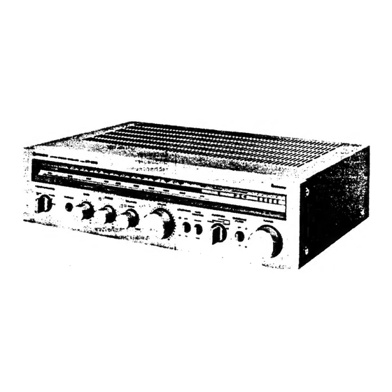
STEREO RECEIVER
April 1980
3A
Advertisement
Table of Contents


Need help?
Do you have a question about the SR-6010 and is the answer not in the manual?
Questions and answers
Toman mucha temperatura los transistores de salida y a volumen alto se corta el sonido
The output transistors of the Hitachi SR-6010 get very hot and cause the sound to cut off at high volume due to excessive power dissipation and thermal buildup. This can be caused by high transient power demands (70W + 70W at 8 ohms), continuous operation at high volume, or inadequate heat dissipation. The amplifier uses a circuit with low distortion and high efficiency, but if the cooling system is insufficient or the load impedance is too low, the transistors may overheat, triggering a thermal protection mechanism that cuts off the sound to prevent damage.
This answer is automatically generated
@Mr. Anderson mil gracias por responder voy a ver si le agrego algún cooler que refrigere los transistores . Hace años que siempre lo usé **** bastante volumen y no fallaba. Un cordial saludo para usted .