Advertisement
Quick Links
Advertisement

Related Manuals for AlgoLaser Alpha MK2


Summary of Contents for AlgoLaser Alpha MK2
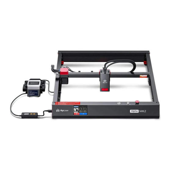
- Page 1 QUICK START GUIDE Laser Engraver Always read the instructions before you start.
- Page 3 CONTENTS Before You Start Machine Assembly How to Use...
- Page 4 Delivery Date Software Computer System parts after receiving the product, please contact our customer service. AlgoLaser will cover the shipping cost of the incorrect product or send the replacement parts. Problem Description, Video & Photo Troubleshooting Support AlgoLaser offers online troubleshooting guides that After submmitting, our engineer will reply helps you to solve problems step-by-step.
- Page 5 Before You Start...
- Page 6 1.1 Disclaimer and safety Guidelines 1. The laser engraver emits laser light. Placing any living body under the laser emission port (marked with an orange warning sign) is strictly forbidden. 2. Patients with photosensitive epilepsy are prohibited from using or approaching the laser engraver.
- Page 7 1.2 Parts List 1.2.1 Machine Front Assembly * 1 Left Y-Axis Assembly * 1 Right Y-Axis Assembly * 1 Rear Panel Assembly * 1 X-Axis Assembly * 1 Motor Extension Shaft * 1 M4X12 Screw * 17 Coupling * 2 M4X16 Screw * 2 USB Cable * 1 Power Cable * 1...
- Page 8 Lens * 1 Laser Shield * 1 (20W) ALM-20BDU Laser Module * 1 Lens *2 Lens Tool *1 Lens Finger AlgoLaser Air pump Guard *2 (AAP 1.0) Seal Rin *2 Focus Assist *1 Thumb Screw *1 Air Pipe *2 Air Pipe *1 1.2.3 Consumable...
- Page 9 Machine Assembly...
- Page 10 / 10 Assemble the Left Y-Axis Assembly Precautions: Be careful not to hit the motherboard of the front panel assembly. Front Assembly Left Y-Axis Assembly M4X12 Screw Step 1: Mount B(Left Y-Axis Assembly) on A(Front Assembly) from the side and secure it with 3 screws in total from the top and the side.
- Page 11 / 10 Assemble the Right Y-Axis Assembly Front Assembly Right Y-Axis Assembly M4X12 Screw Plug the motherboard cable into the motor socket at the bottom of the right Y-axis. Step 2: Mount C(Right Y-Axis Assembly) on A(Front Assembly) from the side and secure it with 3 screws in total from the top and the side.
- Page 12 / 10 Assemble the Rear Panel Assembly M4X12 Screw Rear Panel Assembly M4X12 Screw M4X12 Screw Step 3: Mount D(Rear Panel Assembly) to B(Left Y-Axis Assembly) and C(Right Y-axis Assembly) from the rear and secure them with 6 screws in total from the top and the side. Screw type: M4X12 Screw...
- Page 13 / 10 Assemble the X-Axis Assembly ④ ⑤ ① ② ③ Pull down the lever on the X-axis assembly clamp. ① Place the dovetail groove on the back of the laser module into the corresponding chute of the clamp. ② Lift up the lever to clamp the laser module.
- Page 14 / 10 Assemble the X-Axis Assembly M4X12 Screw M4X12 Screw...
- Page 15 / 10 Assemble the X-Axis Assembly Limit Switch Terminals Interfaces Laser Module Cable Air Pipe Put the air pipe and main cable through the hole under the Y-axis Insert the cable into the port of the mainboard that matches the color of the cable.
- Page 16 / 10 Fasten the belt locking screws Use M4*12 mm screws here Use two M4*16 mm screws here in conjunction with the X-axis tensioner in conjunction with the left and right X-axis to adjust the X-axis belt. tensioners to adjust the Y-axis belt. Here use the left Y-axis tensioner fixing screw for locking.
- Page 17 / 10 Install a motor extension shaft Slide the X-axis assembly + laser module to the rearmost end until they cannot move further. Tighten the two screws on the coupling. Put the motor extension shaft in this position.
- Page 18 / 10 How to Focus Focus Assist Step 22: Place the Focus Assist on the engraving material, ensuring it is positioned beneath the laser module. Gently slide the laser module downward until its edge lightly touches the circular disc on the bottom of the Focus Assist. Once in this position, tighten the Thumb Screw of the laser module to secure it.
- Page 19 / 10 How to Replace the Lens 8.1 Remove Remove the Air Assist Nozzle first, then loosen the Brass Lense Nut with a Lens Tool, pay attention to the rotation direction of the wrench, and take out the old seal ring and lens. 8.2 Install The notched side of the Brass Lense Nut faces up.
- Page 20 How to Use...
- Page 21 3.1 Machine Status Explanation LED Indicator Result Status Action Descriptions Power on Machine quickly Power button short The white LED Power on seeks Machine powers on press <0.5s gradually brightens and for machine zero point Power off Machine shuts Power button long The white LED Power off down Machine powers...
- Page 22 To check the driver installation, follow these steps: ① Find the Device Manager on your computer. ② Navigate to the Ports section. ③ Disconnect the USB cable from the computer. ④ Observe that the new serial port disappears from the Ports section. ⑤...
- Page 23 Visit https://zadig.akeo.ie/ Navigate lower on the page and click The download button Once download is complete, please run the application with Administrator Rights. Once open select List All Devices from the menu Options. Wait for the refresh Select devices starting with “Algo” from the drop-down list .
- Page 24 Driver button, and wait for the installation to complete. When you're done, you can close the Zadig software. The New AlgoLaser X CDC (Interface 0) (COMX) port in Device Manager. Note the COM number might be different in your machine...
- Page 25 3.3 RR2/ARC Connection -- Operation Description Connection: Unplug the Y-axis motor wire from the Y-axis motor and connect it to the corresponding motor jack of RR2/ARC. Connect the control terminal: Use USB or other methods to connect the computer. LaserGRBL: Send "$22=0" in the “Type gcode here ”field. LightBurn: Send the command "$22=0"...
- Page 26 3.4 First-time screen usage instructions: Screen Switch:The screen will automatically power on and off with the machine. First-time Use Guide: A. Language Selection: Choose your preferred language to proceed. lf you skip this step, you can refer to the user manual to set a new language. B.
- Page 27 Engraving via Screen: A. After powering on the machine, click on "Engrave" on the home page to enter the "Engraving Source" page.Select the desired engraving file source, which can be either from the SD card or USB. lf using USB, make sure to insert the USB drive to access the data. B.
- Page 28 D. Engraving Preparation Page: A. Focus Verification: Make sure that the laser is focusing at the correct focal length before clicking "Next". B. Engraving Range: Move the laser with the button. Click "Step" to adjust the moving distance. Observe whether the starting position meets the engraving requirements and whether the range covers the engraved object.
- Page 29 E.Once everything is verified, click "Engrave," and the laser engraving machine will start the process. Wait for the progress to reach 100% to complete the engraving.
- Page 30 3.6 FAQ No response from the machine when being powered on. No power supply: Please check the socket and switch as well as the machine power socket to ensure that they have been correctly plugged with normal power supply. It cannot be connected to computer. USB cable not connected: Please check the USB data cable interface on the machine and computer to ensure it's correctly plugged.The USB interface on the front panel of some desktop computers is invalid, it's...
- Page 32 Follow us! #AlgoLaser AlgoLaser AlgoLaser AlgoLaser AlgoLaser Official AlgoLaser User Group ht t ps : / / alg o la s er. com /su p po r t /...
Need help?
Do you have a question about the Alpha MK2 and is the answer not in the manual?
Questions and answers