Table of Contents
Advertisement
Quick Links
Advertisement
Table of Contents

Summary of Contents for VigilLink VLDT-A2AM150
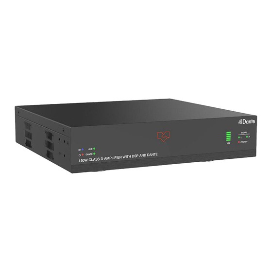
- Page 1 Dante Amplifier VLDT-A2AM150 VER 1.0...
-
Page 2: Table Of Contents
Thank you for purchasing this product For optimum performance and safety, please read these instructions carefully before connecting, operating or adjusting this product. Please keep this manual for future reference. Surge protection device recommended This product contains sensitive electrical components that may be damaged by electrical spikes, surges, electric shock, lighting strikes, etc. -
Page 3: Introduction
1. Introduction This product is designed as a two-channel amplifier using class D amplifier technology. It can be used for powering low impedance (4Ω/8Ω) stereo systems with a maximum power of 2 x 75 Watt, while bridging to a constant voltage (100V and 70V) is possible with a maximum output power of 150 Watt. -
Page 4: Specifications
4. Specifications Technical 1x Dante Network audio input Input 1x LINE balanced stereo 0dBu/10kΩ input 1x Dante Network audio output 1x Stereo or constant voltage 70V/100V speaker output Output 1x LINE balanced stereo output Input Sensitivity Full power@0.775V (0dBu) DC power supply: 2x 75W@4Ω/8Ω; 1x 150W@8Ω; Output Power 1x 150W@70V/100V 27 - 30dB SE/39 - 42dB BTL... -
Page 5: Operation Controls And Functions
Mechanical Housing Front panel: Aluminum; Rear case: Metal Enclosure Color Black 240mm [W]×210mm [D]×44mm [H] Dimensions Weight 1.88Kg DC Input: AC100 - 240V 50/60Hz Power Supply Power Consumption 240W (Max) Operating Temperature 0°C ~ 40°C / 32°F ~ 104°F Storage Temperature -20°C ~ 60°C / -4°F ~ 140°F Relative Humidity 20%~90% RH (non-condensing) -
Page 6: Rear Panel
5.2 Rear Panel 4 / 8 Ω OUT 70 / 100V OUT CLASS 2 WIRING CLASS 2 WIRING Name Function Description Connect to a PC for Web access. The default IP address is LAN port 192.168.0.200. RS-232: Serial control port, used for RS-232 signal pass-through or controlling this product via RS-232 commands. -
Page 7: Dante Web Gui User Guide
6. Dante Web GUI User Guide There is a built-in Dante Web GUI for the amplifier. The operation method is shown as below: Step 1: Connect the amplifier and PC to the same Ethernet Switch with two Network cables. Step 2: Set the Network connection setting of PC to be “Obtain an IP address Automatically”. 1 1 0 Step 3: Open the Dante Controller software on the PC, and find the Dante device on the Routing page, as shown in the figure below. - Page 8 Step 4: Click the Device Info tab to check the IP address of the Dante device. Step 5: Input the IP address of Dante device into your browser on the PC to enter the login interface of the Dante Web GUI. The default usernames and passwords are as below: Username User...
- Page 9 ■ Information Page The Information page provides basic information about the model name, software version and IP information. ■ Preset Page You can set up to 5 preset scenes on the Preset page. ① Preset Name: You can name the preset scene. (Chinese name is not supported.) ②...
- Page 10 Source Select ① Line In: Click “Line In” to select the LINE IN port as the signal input channel for audio output. ② Dante In: Click “Dante In” to select the DANTE port as the signal input channel for audio output.
- Page 11 ■ Network Page Network Configuration: You can set the IP Mode (DHCP/Static), IP Address, Subnet Mask, Gateway, Telnet Port and Domain Name. Note: The Domain Name “HDP-PA150D.local” can be used to login the Web GUI. After setting up, click “Save” to take effect, or you can click “Cancel” to cancel the setting. ■...
-
Page 12: Rs-232 Control Command
7. RS-232 Control Command The product also supports RS-232 command control. Connect the RS-232 port of the product to a PC with a 3-pin phoenix connector cable and an RS-232 to USB cable. The connection method is as follows. Ground 3-pin Phoenix Connector RS-232 RS-232 to USB cable... - Page 13 Function Description Example Feedback Command Code Default Setting r fw version Get Firmware version r fw version MCU 1.1.0 Web 1.1.0 Power on System Initializing... s power on s power on Power on the device Initialization Finished! MCU 1.1.0 Web 1.1.0 Power off s power off Power off the device...
- Page 14 Function Description Example Feedback Command Code Default Setting Increase input:x volume Increase input line s input x vol+ s input 1 vol+ volume: 52 x=[0-2] 0:All, 1:Line, 2:Dante Decrease input:x volume Decrease input line s input 1 vol- s input x vol- volume: 50 x=[0-2] 0:All, 1:Line, 2:Dante s input x mute...
- Page 15 Function Description Example Feedback Command Code Default Setting Get output:x mix mode Output speaker mix: r output x mix r output 1 mix x=[0-3] 0:All, 1:Speaker, 2:Line, Stereo 3:Dante Set output:x delay:y s output 1 delay 50 Set output speaker delay: x=[0-3] 0:All, 1:Speaker, 2:Line, s output x delay y 50ms...
- Page 16 Function Description Example Feedback Command Code Default Setting Get network MAC address MAC: 6C:DF:FB:0C:B3:8E r mac addr r mac addr Set network IP mode to static IP IP mode: Static or DHCP (Please use "s net reboot!" s ip mode x s ip mode 0 x=[0-1] command or repower...
-
Page 17: Connection Diagram
Function Description Example Feedback Command Code Default Setting Password Setting Set admin login password s admin password s admin password admin password: 1234 1234 (x=[16 characters max]) 1234 Get admin login password r admin password r admin password admin password: 1234 Set user login password s user password user password: 1234...
Need help?
Do you have a question about the VLDT-A2AM150 and is the answer not in the manual?
Questions and answers