
Summary of Contents for sunbee SBMPPT40ABT
- Page 1 2.2023 SunbeeSolar MPPT Solar Controller 12/24/36/48V,40/60A SBMPPT40ABT SBMPPT60ABT User Manual Google Play Store Apple App Store Subject to change without notice...
-
Page 2: Table Of Contents
Contents Safety instructions and waiver of liability 1.1 Safety Instructions 1.2 Liability Exclusion Product Overview Dimensions 3.1 The dimensions of S B M P P T 4 0 A B T 3.2 The dimensions of S B M P P T 6 0 A B T Structure &... -
Page 3: Safety Instructions And Waiver Of Liability
1, Safety instructions and waiver of liability 1.1 Safety Instructions The following symbols are used throughout this manual to indicate potentially dangerous conditions or mark important safety instructions. Please take care when meeting these symbols. WARNING: Indicates a potentially dangerous condition. Use extreme caution when performing this task. - Page 4 2, Overview Sunbee Solar MPPT controllers are based on an advanced maximum power point tracking (MPPT) technology. The controller conversion efficiency up to 98%. It comes with several outstanding features, such as: A combination of multiple tracking algorithms enables tracking the maximum power point quickly and accurately Innovative Max Power Point Tracking(MPPT) technology, tracking efficiency >99.9%...
- Page 5 High Voltage Strings and Grid-Tie Modules Another benefit of MPPT technology is the ability to charge batteries with solar arrays of higher nominal voltages. For example, a 12 Volt battery bank may be charged with a 12-, 24-, 36-, or 48-Volt nominal off- grid solar array.
- Page 6 MPPT—Four Charging Stages Sunbee MPPT Controllers have a 4-stage battery charging algorithm for rapid, efficient, and safe battery charging. U(V) Equalize Charge 14.8V 14.5V 13.7V Night MPPT Boost Float Night Charge Charge Charge TIME MPPT Charge In this stage, the battery voltage has not yet reached boost voltage and 100% of available solar power is used to recharge the battery.
-
Page 7: Dimensions
3, Dimensions 3.1 The dimensions of SBMPPT40ABT Unit: mm 136.60 67.10 120.00... -
Page 8: The Dimensions Of Sbmppt60Abt
3.2 The dimensions of SBMPPT60ABT Unit: mm 97.50 186.50 166.00... -
Page 9: Structure & Accessory
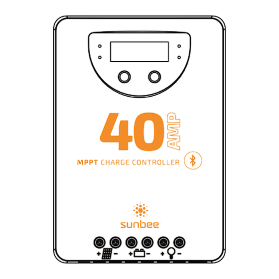
4, Structure & Accessory 4.1 Structure & Characteristics ①Heat Sink —dissipate controller heat ③ ②Plastic Case —Internal protection ③LED & LCD — Display settings and operating status, ④ system parameters ④Key: MENU、OK —Set and view the operating parameters ⑤Temperature Sensor Port —Collect temperature information, Temperature compensation. -
Page 10: Installation
5, Installation CAUTION: Please read all instructions and precautions in the manual before proceeding with the installation It is recommended to remove the protective film cover from the LCD screen before operation 5.1 Installation Notes ⑴ This charge controller must only be used in PV systems in accordance with requirements given in this user manual and the specifications of other system components provided by their manufacturers. -
Page 11: Mounting Location Requirements
5.2 Mounting Location Requirements Do not subject the PV charge controller to direct sunlight or any other heat sources. Protect the PV charge controller from any dust, dirt and moisture. Mount it flat to a vertical wall. Must be a non-flammable material. - Page 12 We strongly recommend connecting a fuse directly to the battery terminal to protect from any short circuit in the battery circuit. PV-modules generate current whenever light shines on them. The generated current is directly proportional to the light intensity. Even low levels of light will deliver the PV-Modules no load, full voltage.
-
Page 13: Wiring Specifications
(mm²/AWG) (mm²/AWG) (mm²/AWG) SBMPPT40ABT 10/8 10/8 SBMPPT60ABT 16/6 16/6 The indicated cable/wire sizes are for reference only. If longer runs between the PV array and the controller or between the controller and the battery are required, larger capacity cables must be used to reduce voltage drop and improve system performance. -
Page 14: Key Function
6.2 Key functions MENU Mode Operating Browse interface Short press OK. Press the MENU and OK key at the same time for 1s, the LCD screen will lock the interface. Static display Press the MENU and OK key again for 1s, the LCD interface will unlock and start scrolling. - Page 15 6.3.2 The interface automatically cycles in the displayed sequence 6.3.3 Press OK to browse the interface...
-
Page 16: Settings
6.3.4 Fault indication Status Icon Description Load off, fault icon display, the LCD screen displays E1. Short circuit Load off, fault icon display, the LCD screen displays E2. Over current Load off, battery level shows empty, fault icon display, Low voltage battery frame flashes, the LCD screen displays E3. - Page 17 6.4.4 Battery type When the LCD shows as displayed at left, press the MENU key for 1s, the icon flashes , now you can set the battery type. Display Battery type GEL(Default) Lithium Flooded Charging Voltage Parameters(Liquid, GEL, AGM) When choosing Liquid, GEL or AGM for battery type, the parameters of boost, equalization and float charge voltage can be set by IoT, RS485 or bluetooth APP.
-
Page 18: Troubleshooting, Protection And Maintenance
Street Lamp Function When the load is set to Dusk to Dawn or Evening mode, the Day/Night threshold voltage and the Day/Night delay time can be set using the Bluetooth APP, and the load can be turned on or off by the test function during the day charging process. -
Page 19: Protection
Protection Protection Description The controller will limit charging power to the rated level. PV Over Current Over-sized PV array will not be able to operate at maximum power point. When PV short circuit occurs, the controller will stop charging. PV Short Circuit Remove it to resume normal operation. -
Page 20: Technical Data
8, Technical Data Item SBMPPT40ABT Max Charging Current System Voltage 12/24V automatic recognition MPPT Charging Voltage before boost or equalization charging stage Boost Voltage 14~14.8/28~29.6V @25℃ (default: 14.5/29V) Equalization Voltage 14~15.0/28~30V@25℃ (default: 14.8/29.6V) (Liquid, AGM) Float Voltage 13~14.5/26~39V @25℃ (default: 13.7/27.4V) Low Volt. - Page 21 Item SBMPPT60ABT Max Charging Current System Voltage 12/24/36/48V automatic recognition MPPT Charging Voltage before boost or equalization charging stage Boost Voltage 14~14.8/28~29.6/42~44.4/56~59.2V@25℃(default:14.5/29/43.5/58V) Equalization Voltage 14~15/28~30/42~45/56~60V@25℃ (default:14.8/29.6/44.4/59.2V) (Liquid, AGM) 13~14.5/26~29/39~43.5/52~58V@25℃(default:13.7/27.4/41.1/54.8V) Float Voltage Battery Low Volt. Disconnect 10.8~11.8/21.6~23.6/32.4~35.4/43.2~47.2V Param- (Default:11.2/22.4/33.6/44.8V) eters Reconnect Voltage 11.4~12.8/22.8~25.6/34.2~38.4/45.6~51.2V(default:12/24/36/48V) Overcharge Protect 15.8/31.3/46.8/62.3V...
-
Page 22: Conversion Efficiency Curves
9.Conversion Efficiency Curves Test conditions Illumination I ntensity: 1000W/m² Temperature: 25℃ Model:SBMPPT40ABT Conversion Efficiency Curves Solar Module MPP Voltage 18V/36V Charging Power(W) Conversion Efficiency Curves Solar Module MPP Voltage 36V/54V/72V 1040 Charging Power (W) - Page 23 Model:SBMPPT60ABT Conversion Efficiency Curves Solar Module MPP Voltage 34V/51V/68V 1100 1300 1500 Charging Power(W) Conversion Efficiency Curves Solar Module MPP Voltage 68V/85V 1000 1250 1500 1750 2000 2250 2500 2750 3000 Charging Power (W)
Need help?
Do you have a question about the SBMPPT40ABT and is the answer not in the manual?
Questions and answers