Table of Contents
Advertisement
GU631A Controller Operation Manual
The clarification of notation used within this manual:
WARNING:
A WARNING indicates a potentially hazardous situation which, if not avoided,
could result in death, serious personal injury or property damage.
CAUTION:
A CAUTION indicates a potentially hazardous situation which, if not avoided,
could result in damage to equipment or property.
NOTE:
A NOTE provides other helpful information that does not fall under the warning
or caution categories.
1
Advertisement
Table of Contents

Summary of Contents for JNH GU631A
- Page 1 GU631A Controller Operation Manual The clarification of notation used within this manual: WARNING: A WARNING indicates a potentially hazardous situation which, if not avoided, could result in death, serious personal injury or property damage. CAUTION: A CAUTION indicates a potentially hazardous situation which, if not avoided, could result in damage to equipment or property.
- Page 2 GU631A Controller Operation Manual WARNING: Read this entire manual pertaining to the work to be performed before installing, operating, or servicing this controller. Practice all plant and safety instructions and precautions. Failure to follow instructions can cause personal injury and/or property damage.
-
Page 3: Table Of Contents
GU631A Controller Operation Manual Contents Description ............................4 The Outline Dimensional Drawings and Controller wiring ............5 Panel Operation..........................8 Control and Operation Instruction....................10 Measure and Display Data......................18 Pre-alarm and Shutdown Alarm ....................19 Parameter Settings........................25 Installation Guide ..........................52 LCD display and Menu System ....................65... -
Page 4: Description
GU631A Controller Operation Manual 1. Description GU631A is a new generation Automatic Mains (Utility) Failure module for single Genset, which adopts bran-new outline configuration, focus on the requirements of customers, and perfectly improves the performance of controller. It fully meets the auto control requirements of different kinds of Genset for user or special assembly factory. -
Page 5: The Outline Dimensional Drawings And Controller Wiring
GU631A Controller Operation Manual 2. The Outline Dimension Drawings and Controller Wiring 2.1 Following Details: Module Dimensions W192mm×H144mm Panel Cutout W174mm×H126mm Thickness D56mm (without connection) - Page 6 GU631A Controller Operation Manual 2.2 Terminal Connections: Pin no. Function Description Signal GEN. V input 0-330Vac 1mm² L1-N GEN. V input 0-330Vac 1mm² L2-N GEN. V input 0-330Vac 1mm² L3-N GEN. Neutral 1mm² Not used MAINS V input 0-330Vac 1mm²...
- Page 7 GU631A Controller Operation Manual 2.3 Typical Wiring Diagram...
-
Page 8: Panel Operation
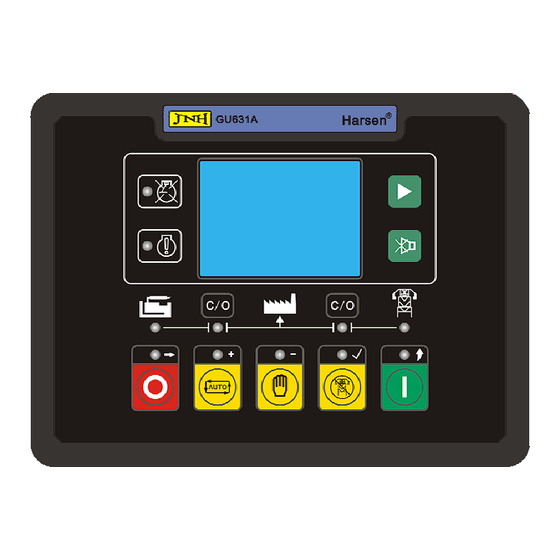
GU631A Controller Operation Manual 3. Panel Operation The operation panel consists of 3 sections: LCD display indicating measurement parameters, LED indicator for common failure, and push buttons for Genset and selection of control modes. LCD with 128*64 pixels can display multi-line data in the same time. LCD also has a backlight so that the operator can clearly read information day or night. - Page 9 GU631A Controller Operation Manual STOP / RESET Button / “→” Move Setting The Push button is used for manually stops the Genset. No matter what mode the controller is running, press and hold this button for 2sec to stop the generator, the mode of the controller will be default to “MAN”...
-
Page 10: Control And Operation Instruction
GU631A Controller Operation Manual 4. Control and Operation Instruction The controller has 3 modes: AUTO, MANUAL and TEST. 4.1 Operation Mode Setting: Operation Description Press and hold the “AUTO” button for 2sec, the LED above the button is illuminated; the controller is running in “AUTO” mode. - Page 11 GU631A Controller Operation Manual NOTE: Above control procedure, assumes that one of configurable inputs has been configured as Mains Aux. Switch Closed and connects the switch’s N.O. Aux. contact to this port. If you do not configure an input as Mains Aux.
- Page 12 GU631A Controller Operation Manual Controller can not implement crank procedure in one of following conditions: A. The generator’s frequency reaches the preset value (configurable cranking cutout value); B. The AC engine speed reaches crank cutout value; C. Generator’s voltage reaches the crank cutout value (optional);...
- Page 13 GU631A Controller Operation Manual NOTE: If you do not configure an input as Mains Aux. Switch Closed then the MCB closed LED illuminates but is only an indication that the MCB close/open relay should have been closed. Stop Failure: When cool down times out, the fuel relay opens and the timer for Stop delay begins. If the...
- Page 14 GU631A Controller Operation Manual NOTE: When the controller is running in “MANUAL” mode, Mains must be normal, or the “C/O” button of Mains will be disabled. Generator starting sequence: Pressing “START” button the fuel relay energises, and operates the fuel solenoid of engine. After...
- Page 15 GU631A Controller Operation Manual 4.5 The start and stop sequence of engine whose fuel solenoid is N. O. type: There are two kinds of fuel solenoids for an engine, one is N.C. type, the valve of this solenoid is closed when the engine is in standby and it can be opened by switching on power;...
- Page 16 GU631A Controller Operation Manual 4.8 The function of forcing start: Reason to add this function to the controller is that when the engine under abnormal conditions, e.g. the battery voltage is too low or ambient temperature is too low, or generator only outputs voltage at a high speed when magnetic pick-up is not used, the Genset cannot be started successfully when it implements the build-up cranking process of controller.
- Page 17 GU631A Controller Operation Manual 4.9 Speed control for actuator motor (optional): Controller with this speed control function controls the speed motor of engine and regulates the size of fuel via continuously output speed raise/lower switch control signal with PID function, making engine’s running speed stabile within the setting range.
-
Page 18: Measure And Display Data
GU631A Controller Operation Manual 5. Measure and Display Data Mains V L1-N L2-N L3-N Ph-N Mains V L1-L2 L2-L3 L3-L1 Ph-Ph Mains frequency Hz (L1) Gen V L1-N L2-N L3-N Ph-N Gen V L1-L2 L2-L3 L3-L1 Ph-Ph Gen frequency Hz (L1) Gen / load 3 phases current I1 I2 I3 Gen / load 3 phases apparent power KVA AL1 AL2 AL3 ∑A... -
Page 19: Pre-Alarm And Shutdown Alarm
GU631A Controller Operation Manual 6. Pre-alarm and Shutdown Alarm 6.1 Pre-alarm (warning) (NOTE: Pre-alarms are non-critical failure conditions and do not affect the operation of the generator system, they serve for drawing the operators’ attention to an undesirable condition so they can remove it to ensure continuous running of the system. - Page 20 GU631A Controller Operation Manual UNDER FREQ: If controller detects that generator’s frequency has fallen below the “GEN-Hz under preALM” after the safety-on timer WARN: UNDER FREQ. has expired, the pre-alarm LED illuminates and the buzzer sounds, LCD displays: GEN. OVER VOLT: If controller detects that any phase output voltage of generator has exceeded the “GEN-V over preALM”...
- Page 21 GU631A Controller Operation Manual ECU ALARM: When using J1939 CAN bus, if the failure detected by ECU, the controller will receive this information from WARN:ECU ALARM the ECU immediately, the pre-alarm LED illuminates and the buzzer sounds, LCD displays: GCB FAILURE: If GCB close/open relay is closed, the timer for GCB closing is activated, when it times out, if the controller does not receive the feed back signal from Gen Aux.
- Page 22 GU631A Controller Operation Manual 6.2 Shutdown Alarm (NOTE: shutdown alarm failures immediately lock out the system and stop the Genset. The failure must be removed and the controller reset before restarting the Genset.) Shutdown Alarm / Description LCD displays START FAILURE: if engine does not fire after the preset...
- Page 23 GU631A Controller Operation Manual GEN. OVER VOLT: After safety-on delay times out, If controller detects that any phase output voltage of generator is higher than “GEN-V over Alarm”, Genset stops, the ALARM:GEN. OVER VOLT Shutdown alarm LED illuminates and buzzer sounds, LCD displays: GEN.
- Page 24 GU631A Controller Operation Manual NOTE: If engine speed signal is derived from generator output voltage frequency, it is used for control and failure protection parameters, for convenience of user, some data is expressed by RPM, RPM = HZ*60 / pair of poles.
-
Page 25: Parameter Settings
GU631A Controller Operation Manual 7. Parameters Setting 7.1 SYSTEM: Items Preset Value Range CT Ratio 1000:5 5:5 to 30000:5 VT Ratio 1.0:1 1.0:1 to 100.0:1 Rated ph-Voltage 1 to 30000VAC Rated current 1000 1.0 to 30000A Rated active power 1.0 to 16000KW... - Page 26 GU631A Controller Operation Manual Voltage Type: There are 5 kinds of voltage type: “Y” 3P4W, “△” 3P4W, 3P3W, 1P3W, 1P2W. 1— “Y” 3P4W (3 phases 4 wires star): 2—“△” 3P4W (3 phases 4 wires angle):...
- Page 27 GU631A Controller Operation Manual 3— 3P3W (3 phases 3 wires): 4— 1P3W (single phase 3 wires): 5— 1P2W (single phase 2 wires):...
- Page 28 GU631A Controller Operation Manual Comm. Address: Used to configure ID address for MODBUS. Each controller on the same MODBUS has a unique communication address. Startup mode: Used to configure the Startup mode of controller when it is powered up. When parameter is configured as “0”, the controller will be in Manual mode when it is powered up.
- Page 29 GU631A Controller Operation Manual Password: There are 3 levels of password (CL0/CL1/CL2) for different users. CL0 for the operator, who can read parameters, start and stop controller. The default setting is no password. CL1 for the technician, who has the authority of CL0 and can modify all parameters, the default setting is “2213”.
- Page 30 GU631A Controller Operation Manual 7.2 GENERATOR: Items Preset Value Range GEN-V under preALM 20 to 200% / not used GEN-V under Alarm not used 20 to 200% / not used GEN-V over preALM 115% 20 to 200% / not used...
- Page 31 GU631A Controller Operation Manual GEN-Hz over Alarm: Used to configure Gen over frequency alarm value, the GEN-Hz over Alarm is inactive when parameter is configured as “not used”. KW Overload preALM: Used to configure the over load pre-alarm value, the KW Overload preALM is inactive when parameter configured as “not used”.
- Page 32 GU631A Controller Operation Manual 7.3 ENGINE: Items Preset Value Range Rated speed 1500RPM 99 to 9999 RPM MPU input 0 NO / 1 YES Fly wheel teeth 5 to 300 Set pickup now Pair of Poles 1 to 4 Fuel mode 0 N.C.
- Page 33 GU631A Controller Operation Manual Fly wheel teeth: Used to configure there are how many teeth on the fly wheel. Set pickup now: If user does not know the fly wheel teeth, to calculate the fly wheel teeth automatically via the measuring Gen frequency and MPU frequency.
- Page 34 GU631A Controller Operation Manual The parameters appendix of HET sensor: VDO 120℃: T(℃) T(℉) R(Ω) VDO 150℃: T(℃) T(℉) R(Ω) Datcon: T(℃) T(℉) R(Ω) Murphy: T(℃) T(℉) R(Ω) 1029 PT100: -100 T(℃) T(℉) -148 R(Ω) Pre-set 1: T(℃) T(℉) R(Ω) Pre-set 2: T(℃)
- Page 35 GU631A Controller Operation Manual P-sensor type: Used to configure the type of LOP sensor. Optional kinds of built-in LOP sensors in controller. Code Mode Note close for low oil pressure open for low oil pressure VDO 5 bar VDO 10 bar...
- Page 36 GU631A Controller Operation Manual Pre-set 2: 10.0 P(Bar) P(PSI) 14.5 29.0 43.5 58.0 72.5 87.0 101.5 116.0 130.5 145.0 R(Ω) Pre-set 3: 10.3 P(Bar) P(PSI) R(Ω) Pre-set 4: P(Bar) P(PSI) 14.5 29.0 43.5 58.0 72.5 87.0 101.5 116.0 130.5 R(Ω) NOTE: “Configurable”...
- Page 37 GU631A Controller Operation Manual Crank cutout volt: The crank disconnect voltage Expressed by percentage, use “Rated ph-voltage” as factor. Crank cutout ALT-V: The crank cutout Charger voltage, signal is from the W/L terminal of charger. When parameter is configured as “not used”, this function is inactive.
- Page 38 GU631A Controller Operation Manual Stop delay: The maximum time permit for the engine stop. After the fuel relay output is de-energised (fuel relay output is energised for N.O. type fuel valve), fail to stop delay timer begins, when it time’s out if controller detects generator’s voltage exceeds crank cutout voltage, or the speed exceeds crank cutout RPM, or LOP switch is open, or oil pressure exceeds crank cutout oil pressure, then stop failure occurs.
- Page 39 GU631A Controller Operation Manual ALT. low preALM: Used to configure the low charger voltage value. Voltage signal is derived from the excitation winding of charger. If this parameter is configured as “not used”, the function would be inactive. EX. Crank permit: Used to configure the permit of external crank.
- Page 40 GU631A Controller Operation Manual 7.4 Configurable Inputs and Outputs: Items Preset Value Range D-Input 1 1 to 20 / not used 1 to 20 / not used D-Input 2 1 to 20 / not used D-Input 3 1 to 20...
- Page 41 GU631A Controller Operation Manual Menu descriptions: D-Input*: There are 7 configurable digital inputs. Optional items as following: Code Optional Functions Note Low level is active. When it is active, pre-alarm LED Pre-alarm (warning) illuminates and buzzer sounds, LCD displays: warning: D-input* Low level is active.
- Page 42 GU631A Controller Operation Manual Enter data according to the curve of the fuel sensor, configurable 1 only can be set through the software, configurable 2 can be set through both the push button on the front panel and software. Fuel pump ON: Used to configure the low fuel level value, the configurable relay output which is defined as “fuel...
- Page 43 GU631A Controller Operation Manual Pre-heat ON: Used to configure the under engine temperature value, the configurable relay output which is configured as “preheat” would be energised if it reaches this value. To active this function, the “A-sensor 2 use” is required to configure as “1” preheat.
- Page 44 GU631A Controller Operation Manual User relay *: There are 5 configurable output relays. Optional functions as following : Code Definition not used Over current trip Common alarm Common pre-alarm (warning) Idle relay N.C. Preheat relay Speed up Speed down Fuel pump control GEN.
- Page 45 GU631A Controller Operation Manual Over speed alarm Under frequency alarm Over frequency alarm GEN. under voltage alarm GEN. over voltage alarm KW overload alarm P-Sensor open alarm Configurable D-input 1 active Configurable D-input 2 active Configurable D-input 3 active Configurable D-input 4 active...
- Page 46 GU631A Controller Operation Manual 7.5 Configurable sensor data Item Preset Value Range PRES. Sensor 1 PRES. Sensor 2 TEMP. Sensor 1 TEMP. Sensor 2 Fuel Level Sensor Menu Descriptions: PRES. Sensor 1: Corresponds to the “configurable 2” in the “LOP Sensor type”.
- Page 47 GU631A Controller Operation Manual Mains-V High Alarm: Used to configure high Mains voltage alarm value, the Mains-V high Alarm is inactive when parameter configured as “not used”. Expressed by percentage, use “Rated ph-voltage” as factor. Mains-Hz low Alarm: Used to configure low Mains frequency alarm value, the Mains-Hz low Alarm is inactive when parameter configured as “not used”.
- Page 48 GU631A Controller Operation Manual Start time: Used to configure the start time when controller is active in exercise run scheduler. Run duration: Used to configure the duration when controller is active in exercise run schedule, the scheduler mode will be reset after run duration has expired.
- Page 49 GU631A Controller Operation Manual 7.9 SPEED CONTROL Items Preset Value Range Proportional gain 10.0 0.1 to 100.0 Integral gain 1.0s 0.1 to 100.0s Derivative ratio 1.0s 0.1 to 100.0s Deadband 0.2Hz 0.1 to 9.9Hz Time pulse minimum 0.2s 0.1 to 2.0s...
- Page 50 GU631A Controller Operation Manual 7.10 CALIBRATION MENU Items Preset Value Range 10.1 GEN. V1 offset -9.9% to 9.9% 10.2 GEN. V2 offset -9.9% to 9.9% 10.3 GEN. V3 offset -9.9% to 9.9% 10.4 Current I1 offset -9.9% to 9.9% 10.5 Current I2 offset -9.9% to 9.9%...
- Page 51 GU631A Controller Operation Manual Mains V1 offset: Used to modify the measured value display of Mains Phase 1 voltage. Reference to the Rated ph-voltage. Mains V2 offset: Used to modify the measured value display of Mains Phase 2 voltage. Reference to the Rated ph-voltage.
-
Page 52: Installation Guide
GU631A Controller Operation Manual 8. Installation Guide 8.1 The cutout dimensional drawing installed on panel as follows: 1 74 m m 1 72 m m Cutout dimension: 174mm (W) x 126mm (H). The controller is fixed by 6 special fittings. - Page 53 GU631A Controller Operation Manual 8.2.2 Power supply: Power specification: 8-35Vdc continuous DC voltage range Max. operating current @12V, 310mA; @24V, 155mA 0V for 80ms, assuming dc supply was at least 10V before Cranking dropouts dropout and recovers to 5V, controller can be normally operated dispenses with additional aux.
- Page 54 GU631A Controller Operation Manual The connection for single pole / 2 poles sensor: NOTE: For ensuring the accuracy of sensor please reduce the cable resistance between controller and sensor as much as possible, the cross section area of cable should not be less than 2.5mm When single pole sensor is used, the terminal #16 must be directly connected to the generator’s earth point, but not to the control panel or other...
- Page 55 GU631A Controller Operation Manual 8.2.5 Typical connection for voltage input and current that corresponding to difference generator winding: 3P4W (3 phases 4 wires), CT measure at Gen side Measure and Display Data “Y” 3P4W (3 phases 4 wires star) “△” 3P4W (3 phases 4 wires angle)
- Page 56 GU631A Controller Operation Manual 3P4W (3 phases 4 wires), CT measure at Load side Measure and Display Data “Y” 3P4W (3 phases 4 wires star) “△” 3P4W (3 phases 4 wires angle) Mains 3 phases V L1-N L2-N L3-N Mains 3 phases V...
- Page 57 GU631A Controller Operation Manual 3P3W (3 phases 3 wires), CT measure at Gen side Measure and Display Data Mains 3 phases V L1-L2 L2-L3 L3-L1 Ph-Ph Mains frequency Hz (L1) Gen 3 phases V L1-L2 L2-L3 L3-L1 Ph-Ph Gen frequency Hz (L1) Gen 3 phases current I1 I2 I3 Gen 3 phases apparent power ∑A...
- Page 58 GU631A Controller Operation Manual 3P3W (3 phases 3 wires), CT measure at Load side Measure and Display Data Mains 3 phases V L1-L2 L2-L3 L3-L1 Ph-Ph Mains frequency Hz (L1) Gen 3 phases V L1-L2 L2-L3 L3-L1 Ph-Ph Gen frequency Hz (L1) Load 3 phases current I1 I2 I3 Load apparent power ∑A...
- Page 59 GU631A Controller Operation Manual 1P3W (single phase 3 wires), CT measure at Gen side Measure and Display Data Mains V L1-N L2-N Ph-N Mains V L1-L2 Ph-Ph Mains frequency Hz (L1) Gen V L1-N L2-N Ph-N Gen V L1-L2 Ph-Ph...
- Page 60 GU631A Controller Operation Manual 1P3W (single phase 3 wires), CT measure at Load side Measure and Display Data Mains V L1-N L2-N Ph-N Mains V L1-L2 Ph-Ph Mains frequency Hz (L1) Gen V L1-N L2-N Ph-N Gen V L1-L2 Ph-Ph...
- Page 61 GU631A Controller Operation Manual 1P2W (single phase 2 wires), CT measure at Gen side Measure and Display Data Mains V L1-N Ph-N Mains frequency Hz (L1) Gen V L1-N Ph-N Gen frequency Hz (L1) Gen current I1 Gen phase apparent power A...
- Page 62 GU631A Controller Operation Manual 1P2W (single phase 2 wires), CT measure at Load side Measure and Display Data Mains V L1-N Ph-N Mains frequency Hz (L1) Gen V L1-N Ph-N Gen frequency Hz (L1) Load current I1 Load phase apparent power A...
- Page 63 GU631A Controller Operation Manual 8.2.6 The connection of configurable digital inputs There are 7 configurable Inputs, which used for monitoring and control status, all of the inputs adopt electrical isolation, and controller internal provides 8vdc power supply, no need an additional power.
- Page 64 GU631A Controller Operation Manual 8.2.7 Connection for the configurable output relays There are 7 relay outputs, except fuel and crank relays which are fixed function, other relays’ function all can be configured by user. NOTE: Terminal #19 is the common port for RL1 to RL6, and it is connected to power positive.
-
Page 65: Lcd Display And Menu System
GU631A Controller Operation Manual 9. LCD displays and Menu System LCD displays measuring parameters: Use a back-light graphic LCD to display data and information. Each page can display multi-row information simultaneously, the above 4 rows display measuring data, the last row displays status information, press “... - Page 66 GU631A Controller Operation Manual Operation Description G. P=0KW G. A=0KVA This page displays Gen power and average power factor, press G. Q=0KVAr “ ” to scroll next page. G. PF=1.00 Run Hour=0.0 COUNTERS=0 This page displays running hours, crank attempt, and Auxiliary sensor level, press “...
- Page 67 GU631A Controller Operation Manual For example: (setting CT ratio at 500: 5, then CT should be configured as 500) Operation Description [SETTING] 0. QUIT Press and hold “ ” 2sec, enter into parameters setting menu, 1. SYSTEM then LCD displays: 2.
- Page 68 GU631A Controller Operation Manual For example: (resume parameters of controller to factory default) Operation Description [SETTING] 0. QUIT Press and hold “ ” 2sec, enter into parameters settings menu, 1. SYSTEM then LCD displays: 2. GENERATOR 3. ENGINE [SYSTEM] 12. Telephone 1 NO.
-
Page 69: Technical Specification
GU631A Controller Operation Manual 10. Technical Specification 10.1 AC voltage: Measurement True RMS Phase to Neutral 15 to 330VAC Phase to Phase 25 to 572VAC Input resistance per line 5.0 MΩ Max power wastage per line <0.1W Accuracy Display 0 to 600KV 10.2 AC voltage frequency:... - Page 70 GU631A Controller Operation Manual 10.6 Configurable relay outputs: Fuel relay 16A/30Vdc Start relay 16A/30Vdc Aux relay 3A/30Vdc 10.7 Charge failure input: Voltage range 0 to 35Vdc Accuracy Max output current @12V 120mA, @24V 240mA 10.8 Analog Inputs: Number Sensor type...
Need help?
Do you have a question about the GU631A and is the answer not in the manual?
Questions and answers