Table of Contents
Advertisement
Quick Links
Use a white CLEANING PAPER (Parts No. 857P007O20) or a HEAD CLEANING PEN KIT2
(Parts No. 859D160O20) for cleaning of the THERMAL HEAD.
Do not use a russet CLEANING PAPER (Parts No. 857P001O10).
It may damage the THERMAL HEAD.
Before servicing this chassis, it is important that the service person reads "SAFETY PRECAUTIONS" and "PRODUCT
SAFETY NOTICE" in this service manual.
Copyright C 2006 Mitsubishi Electric Corporation All Rights Reserved.
BRT
CONT
LOCK
OPEN
This model was converted to be RoHS-
compliant during manufacturing. Serial
numbers for this model are provided as
follows:
Non-RoHS-compliant products
•
Serial no. 0001001 to 6001000
RoHS-compliant products
•
Serial no. 6001001 and later
Provide servicing referring to "NOTES
FOR SERVICING RoHS-COMPLIANT
PRODUCTS" described in the service
manual.
Pb Solder, Pb Joints, Pb PCA
This product uses lead-free solder
on the circuit boards. For repairing
circuit boards, see "Precautions for
resoldering" in this Service Manual.
CAUTION
MITSUBISHI ELECTRIC
DIGITAL MONOCHROME PRINTER
COPY
BRT/CONT
DOWN
UP
LOCK
FEED
2006
MODEL
P93DW
Advertisement
Table of Contents

Related Manuals for Mitsubishi Electric P93DW


Summary of Contents for Mitsubishi Electric P93DW
- Page 1 "Precautions for resoldering" in this Service Manual. CAUTION Before servicing this chassis, it is important that the service person reads “SAFETY PRECAUTIONS” and “PRODUCT SAFETY NOTICE” in this service manual. MITSUBISHI ELECTRIC Copyright C 2006 Mitsubishi Electric Corporation All Rights Reserved.
-
Page 2: Notes For Servicing Rohs-Compliant Products
NOTES FOR SERVICING RoHS-COMPLIANT PRODUCTS Follow the notes and instructions below when servicing RoHS-compliant products. 1. For RoHS-compliant products, be sure to use RoHS-compliant service parts. Check the presence of <G> marking on the rating plate to distinguish RoHS- compliant product from non-RoHS-compliant product. <G>... -
Page 3: Specifications
SPECIFICATIONS • Power Supply and Power Consumption : 100 to 240 V AC, 50 / 60 Hz, 1.5 to 0.8 A : 1,280 pixels (H) × 1,280 pixels (V) (Standard) • Dot Resolution (Max.1,280 pixels × 5760 pixels ) • Printing Speed : Approx. -
Page 4: Table Of Contents
CONTENTS – FILE “COVERPGE” – NOTES FOR SERVICING RoHS-COMPLIANT PRODUCTS ·····································································2 SPECIFICATIONS ·······································································································································3 CONTENTS ···············································································································································4 – FILE “INSTBOOK” – FEATURES AND FUNCTIONS ···················································································································1 INSTALLATION OF PAPER ························································································································2 EXAMPLE OF CONNECTION/SETTING OF SWITCHES ··········································································3 ERROR DISPLAY ········································································································································3 STATUS AND MODES ································································································································5 USE OF CLEANING PAPER ·······················································································································5 –... -
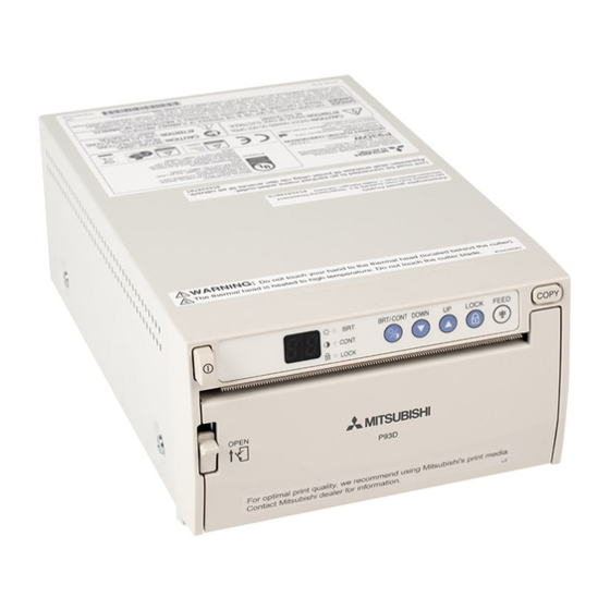
Page 5: Features And Functions
FEATURES AND FUNCTIONS Front Panel Rear Panel 6 7 8 9 COPY BRT/CONT DOWN LOCK FEED CONT LOCK 1 2 3 4 DIP SW AC LINE DIP SW FUNCTION TABLE OPEN FUNCTION LOCK SW-ON SW-OFF POTENTIAL EQUALIZATION TERMINAL This is used to equalize the potential of the equipment connected to this unit. -
Page 6: Installation Of Paper
INSTALLATION OF PAPER Moisture, fingerprints or dust on the When setting the paper, observe the following Pull out the paper end. paper surface may cause a noise at precautions to prevent paper jam. printing or deterioration in print quality. Set the paper by the follow- •... -
Page 7: Example Of Connection/Setting Of Switches
EXAMPLE OF CONNECTION / SETTING OF SWITCHES ERROR DISPLAY Connecting to various equipment with USB interface such as In case of an error in the unit during operation, you are warned medical equipment and personal computer. by an alarm tone or the LED indicator. Symptom/Remedy Connection Cause/Error display... - Page 8 Cause/Error display Symptom/Remedy Cause/Error display Symptom/Remedy 2 2 2 2 2 4 4 4 4 4 [Symptom] Door error [Symptom] No paper • When the door opens, an alarm tone is heard. • When the paper runs out or the paper is not installed, printing becomes impossible and an alarm tone is heard.
-
Page 9: Status And Modes
USE OF CLEANING PAPER STATUS AND MODES When the thermal head is dirty with dust, etc., white spots or stripes may appear on the print. In this case, clean the thermal head by the following procedure BY USING THE Set state/Mode LED display Contents of LED display SUPPLIED CLEANING PAPER. -
Page 10: Safety Precautions
SAFETY PRECAUTIONS NOTICE : Observe all cautions and safety notes located inside the cabinet and on the chassis. LEAKAGE CURRENT CHECK Before returning the printer to the customer, it is recommended that leakage current be measured according to the following methods. -
Page 11: Precautions For Resoldering
PRECAUTIONS FOR RESOLDERING Lead-free solder is handled in a different way from eutectic solder. See below for details. How to distinguish circuit boards using lead-free solder from those using eutectic solder Circuit boards using lead-free solder A mark of Solder, Joints, PCA or LFS (for limited marking space) is printed near the board assembly number on the component side. -
Page 12: Pcb Location
(Converted to be RoHS-compliant during manufacturing) PCB LOCATION [Non-RoHS-compliant products] - Serial No. 0001001 to 6001000 - Rating plate doesn’t bear <G> marking. - The parts catalog below includes non-RoHS-compliant parts. To prevent unintentional use of non-RoHS-compliant parts for RoHS-compliant products, don't use any parts listed in the parts list below for RoHS-compliant products. - Page 13 (Converted to be RoHS-compliant during manufacturing) [RoHS-compliant products] - Serial No. 6001001 and later - Rating plate bear <G> marking. - Parts listed below are all RoHS-compliant. - For the products having the serial numbers shown above, use RoHS-compliant parts only. PCB-MAIN (936B217O04) PCB-P2...
-
Page 14: Disassembly
DISASSEMBLY Removal of the top panel assy 1. Remove five screws (q to t) that are securing the top panel assy and remove the top panel assy in the direction of the arrow A as shown in Fig. 1. Removal of the door 1. - Page 15 Removal of the PCB-MAIN 1. Remove the top panel assy. (See Fig. 1.) 2. Disconnect all the connectors on the PCB-MAIN. 3. Remove one screw (q) that are securing the rear panel as shown in Fig. 3. 4. Remove four screws (w to t) that are securing the PCB-MAIN and remove the PCB-MAIN as shown in Fig. 3. PCB-MAIN Rear panel Fig.
-
Page 16: Removal Of The Power Unit And Pcb-Power
Removal of the power unit and PCB-POWER 1. Remove the top panel assy and PCB-MAIN. (See Figs. 1 and 3.) 2. Remove four screws (q to r) that are securing the rear panel and remove the rear panel as shown in Fig. 4. 3. - Page 17 Adapter IC holders IC holders 3 Insulator Insulator Insulation tubes Insulation tubes IC holder 3 IC holder Heatsink Heatsink Insulators Fig. 6 - 8 -...
-
Page 18: Removal Of The Pcb-Led And Pcb
Removal of the PCB-LED and PCB-SW 1. Remove the top panel assy, door, and front panel unit. (See Figs. 1 and 2.) 2. Remove two screws (q and w) that are securing the PCB-LED and remove the PCB-LED as shown in Fig. 7. Note: When attaching the PCB-LED, put the raised portion of the EN holder into the hole in the cutter. -
Page 19: Removal Of The Step Motor
Removal of the step motor 1. Remove the printer unit. (See Figs. 8 ) 2. Remove two screws (q and w) that are securing the step motor and remove the step motor as shown in Fig. 9. Note: When attaching the step motor, move it in the direction of the arrow to eliminating any gap and secure it with the screws. -
Page 20: Removal Of The Sp Sensor Unit (Light Receivers Of The Paper Detectors 1 And 2)
Removal of the SP sensor unit (light receivers of the paper detectors 1 and 2) 1. Remove the top panel assy, door, front panel unit, and platen roller unit. (See Figs. 1, 2, and 10.) 2. Remove two screws (q and w) that are securing the paper guide shown in Fig. 11 and raise the paper guide in the direction of the arrow. -
Page 21: Removal Of The Head Assy
Removal of the head assy 1. Remove the top panel assy, door, front panel unit, and switch lever,. (See Figs. 1, 2, and 4.) 2. Remove two screws (q and w) that are securing the upper plate and remove the upper plate as shown in Fig. 12. Note: The upper plate is retained by the head springs. -
Page 22: Lead Dress
LEAD DRESS The Lead Wires to be clamped are listed in the table below. Note: The inner wires are clamped so that they do not come close to heat generating. After servicing route all wires in their original position. Lift and clamp the parts shown by white letters on a black background in the figures. Run the PR lead wire under the SW and MP lead wires. -
Page 23: Chip Parts Replacement
CHIP PARTS REPLACEMENT CHIP PARTS REPLACEMENT 2. Removal of Chip Parts (Transistors) Some resistors, shorting jumpers (0Ω resistor), ceramic A. Melt the solder of one lead. Lift the side of that lead capacitors, transistors and diodes are chip parts. upward. When replacing these parts, note the following cautions. -
Page 24: Cleaning
CLEANING Cleaning using the head cleaning pen ¡ ¡ Slide the head cleaning pen along the heat generating part of the thermal head to clean the thermal head. Thermal head Heat generating part Head cleaning pen Fig.1 Head cleaning pen Head cleaning pen kit 2 (Part No.859D160O20) Fig.2 Dirt or dust on the platen roller may cause print failure. -
Page 25: Service Mode
Install the print paper when you carry out the procedures described in " SERVICE MODE, " " FUNCTION MODE, " " ADJUSTMENT OF PAPER DETECTION LEVEL, " and " E PROM INITIALIZATION. " SERVICE MODE How to activate the service mode Operation LED indication 1. - Page 26 Service mode list The table below describes each setting mode in the service mode. LED indication Description Setting mode Left Right Standby You can select any built-in test pattern. Press the COPY button to print the selected test pattern. The setting value is stored in nonvolatile memory. (Basically the test patterns are 1280 x 1280 pixels in size.
-
Page 27: Function Mode
FUNCTION MODE How to activate the function mode Operation LED indication 1. Turn off the POWER button. 2. While holding down the COPY button and the BRT/CONT button together, turn on the POWER button. (Make sure that the LED indication changes to " ".) 3. -
Page 28: How To Select The Setting Mode
How to select the setting mode 1. Activate the function mode. 2. Select your desired setting mode by pressing the LOCK button while checking the LED indication. [Note] The setting mode varies in the order shown below. Setting mode LED indication Standby Paper type setting Paper saving setting... - Page 29 Function mode list *The table below describes each setting mode in the function mode. LED indication Setting mode Description Left Right Standby The setting of the personal computer applies when the right LED indicates " ", and the high glossy print paper is used when it indicates "...
- Page 30 LED indication Description Setting mode Left Right You can adjust the brightness of the printed image. The setting of the personal computer applies when the right LED indicates " ". When it indicates any value other than " ", the brightness is set to the level corresponding to the indicated value.
-
Page 31: Adjustment Of Paper Detection Level
ADJUSTMENT OF PAPER DETECTION LEVEL This adjustment optimizes the sensitivity of the paper sensor. Check the LED indication following the procedure below. Operation LED indication 1. Activate the service mode. 2. Press the LOCK button three times. 3. Remove the print paper. 4. -
Page 32: Test Printing
TEST PRINTING Operation LED indication 1. Turn on the POWER button. 2. While holding down the DOWN button, press the COPY button. Print example TEST PRINT F / W VERSION D301021b E2C4 TABLE VERSION 93D10200 1FED LOADER VERSION 93L1031a 921B ♦♦♦♦♦♦... -
Page 33: Electrical Adjustments
ELECTRICAL ADJUSTMENTS Preparation for adjustment MODE switch, etc. Adjustment point Setting LOCK Reserve switch Reserve Reserve Power source On/Off Front-panel Paper Print paper loaded Input/output terminal No connection AC in Power input 120V±5% Measuring devices and tools General electric tools Digital voltmeter Locations PCB-POWER (Component side) -
Page 34: Power Circuit
[ Power circuit ] Adjustment purpose To increase the primary voltage to 380 V to accept AC input of 100 to 1. Increased primary 240 V. voltage Symptom when The consumption power increases. incorrectly adjusted Measuring 1. Supply a voltage of 120 ± 6 V to the AC power source. Digital voltmeter instrument 2. - Page 35 List of the head resistance and applied voltage (E2) Resistance Resistance Last 1th digit [Ω] Upper 3 digits [Ω] 4500 22.135 22.137 22.140 22.142 22.145 22.147 22.149 22.152 22.154 22.157 4510 22.159 22.162 22.164 22.166 22.169 22.171 22.174 22.176 22.179 22.181 4520 22.183...
- Page 36 Resistance Resistance Last 1th digit [Ω] Upper 3 digits [Ω] 4860 22.993 22.995 22.998 23.000 23.002 23.005 23.007 23.009 23.012 23.014 4870 23.016 23.019 23.021 23.023 23.026 23.028 23.030 23.033 23.035 23.037 4880 23.040 23.042 23.044 23.047 23.049 23.051 23.054 23.056 23.058 23.061...
- Page 37 Resistance Resistance Last 1th digit [Ω] Upper 3 digits [Ω] 5220 23.820 23.822 23.825 23.827 23.829 23.831 23.834 23.836 23.838 23.840 5230 23.843 23.845 23.847 23.849 23.852 23.854 23.856 23.858 23.861 23.863 5240 23.865 23.867 23.870 23.872 23.874 23.876 23.879 23.881 23.883 23.885...
- Page 38 Resistance Resistance Last 1th digit [Ω] Upper 3 digits [Ω] 5580 24.619 24.622 24.624 24.626 24.628 24.630 24.633 24.635 24.637 24.639 5590 24.641 24.643 24.646 24.648 24.650 24.652 24.654 24.657 24.659 24.661 5600 24.663 24.665 24.667 24.670 24.672 24.674 24.676 24.678 24.681 24.683...
- Page 39 Resistance Resistance Last 1th digit [Ω] Upper 3 digits [Ω] 5940 25.394 25.396 25.398 25.400 25.402 25.404 25.406 25.408 25.411 25.413 5950 25.415 25.417 25.419 25.421 25.423 25.425 25.428 25.430 25.432 25.434 5960 25.436 25.438 25.440 25.442 25.444 25.447 25.449 25.451 25.453 25.455...
-
Page 40: Packing Parts
PACKING PARTS ACCESSORY - 1 -... - Page 41 (Converted to be RoHS-compliant during manufacturing) [Non-RoHS-compliant products] - Serial No. 0001001 to 6001000. - Rating plate doesn’t bear <G> marking. - The parts catalog below includes non-RoHS-compliant parts. To prevent unintentional use of non-RoHS-compliant parts for RoHS-compliant products, don't use any parts listed in the parts list below for RoHS-compliant products. ITEM PARTS NO.
-
Page 42: Label Attaching Position
LABEL ATTACHING POSITION [Note] Attach the label such that the characters on the label is perpendicular to the arrow. TOP VIEW BOTTOM VIEW 7 mm 6 mm FRONT Place the label at the center along the front ridge of the paper holder. Label Type q Name label w Do not touch to the CUTTER and the THERMAL HEAD... - Page 43 (Converted to be RoHS-compliant during manufacturing) PARTS LIST [Non-RoHS-compliant products] - Serial No. 0001001 to 6001000 - Rating plate doesn’t bear <G> marking. - The parts catalog below includes non-RoHS-compliant parts. To prevent unintentional use of non-RoHS-compliant parts for RoHS-compliant products, don't use any parts listed in the parts list below for RoHS-compliant products.
- Page 44 * : Warranty return items Non-RoHS : Critical Components SYMBOL PARTS SYMBOL PARTS PARTS NAME DESCRIPTION PARTS NAME DESCRIPTION 442D111O10 EARTH TERMINAL ! C901 189P212O90 C-M-P-AC AC250V/275V 0.22µF-M 439P013O20 LIMIT SWITCH ! C903 189P213O20 C-M-P-AC 0.47µF-M ! C905 189P212O50 C-M-P-AC AC250V/275V 0.047µF-M 685C002O40 RETAINING RING ! C906...
- Page 45 (Converted to be RoHS-compliant during manufacturing) [RoHS-compliant products] - Serial No. 6001001 and later - Rating plate bear <G> marking. - Parts listed below are all RoHS-compliant. - For the products having the serial numbers shown above, use RoHS-compliant parts only. * : Warranty return items : Critical Components SYMBOL PART...
- Page 46 * : Warranty return items RoHS : Critical Components SYMBOL PART SYMBOL PART PART NAME DESCRIPTION PART NAME DESCRIPTION C801 181P352O10 ELECTROLYTIC CAPACITOR 04W 16V 22µF-M 936D264O01 SW PCB ASSY C814 181P352O10 ELECTROLYTIC CAPACITOR 04W 16V 22µF-M C818 181P351O50 ELECTROLYTIC CAPACITOR 10V 220µF-M MECHANICAL PARTS ! C901 189P212O90 C-M-P-AC...
- Page 47 EXPLODED - 1 -...
- Page 48 EXPLODED VIEW...
- Page 49 - 3 -...
-
Page 50: Parts List
PARTS LIST [EXPLODED VIEW] In order to expedite delivery of replacement part orders. Specify : 1. Model number/Serial number 2. Part number and Description 3. Quantity Unless full information is supplied, delay in execution of orders will result. mark : Warranty return items : Critical components (Converted to be RoHS-compliant during manufacturing) [Non-RoHS-compliant products]... - Page 51 Non-RoHS ITEM PARTS NO. ADDRESS PARTS NAME DESCRIPTION ♦ PRINTER UNIT (956C163O01) 734C071O10 KNOB LEVER ♦ BASE CHASSIS (591A077O10) 771D099O10 ABS GR-1000 ♦ WASHER (683D152O10) ! 37 936B204O01 PCB-MAIN ♦ TOP HOLDER (597C032O10) ♦ DATA COVER (598D468O10) ♦ REAR PANEL (597C031O20) ♦...
- Page 52 [EXPLODED VIEW] In order to expedite delivery of replacement part orders. Specify : 1. Model number/Serial number 2. Part number and Description 3. Quantity Unless full information is supplied, delay in execution of orders will result. mark : Warranty return items : Critical components (Converted to be RoHS-compliant during manufacturing) [RoHS-compliant products]...
- Page 53 RoHS ITEM PARTS NO. ADDRESS PARTS NAME DESCRIPTION ♦ PRINTER UNIT (956C163O03) 734C071O10 KNOB LEVER ♦ BASE CHASSIS (591A077O10) 771D099O10 ABS GR-1000 ♦ WASHER (683D158O10) ! 37 936B217O04 PCB-MAIN ♦ TOP HOLDER (597C032O10) ♦ DATA COVER (598D468O10) ♦ REAR PANEL (597C031O20) ♦...
- Page 54 PRINTER UNIT EXPLODED VIEW : APPLY GEAR GREASE (MOLYTONE No.2, 859D055O70) : APPLY OIL (FL-955)
- Page 55 - 9 -...
-
Page 56: Printer Unit Exploded View
PARTS LIST [PRINTER UNIT EXPLODED VIEW] In order to expedite delivery of replacement part orders. Specify : 1. Model number/Serial number 2. Part number and Description 3. Quantity Unless full information is supplied, delay in execution of orders will result. mark : Warranty return items : Critical components (Converted to be RoHS-compliant during manufacturing) - Page 57 Non-RoHS ITEM PARTS NO. ADDRESS PARTS NAME DESCRIPTION ♦ PINCH SPRING (473D109O10) ♦ LOCK BUSH (622C098O10) ♦ PINCH SHAFT (632D049O10) ♦ PINCH PLATE R (598D483O20) 439P013O20 SH/SR sensor unit(LIMIT SWITCH) head position sensor,door open/close sensor 288P208O20 STEP MOTOR ♦ UP LEVER (598D481O10) 632D097O10 GEAR C...
- Page 58 [PRINTER UNIT EXPLODED VIEW] In order to expedite delivery of replacement part orders. Specify : 1. Model number/Serial number 2. Part number and Description 3. Quantity Unless full information is supplied, delay in execution of orders will result. mark : Warranty return items : Critical components (Converted to be RoHS-compliant during manufacturing) [RoHS-compliant products]...
- Page 59 RoHS ITEM PARTS NO. ADDRESS PARTS NAME DESCRIPTION ♦ LOCK BUSH (622C098O10) ♦ PINCH SHAFT (632D049O10) ♦ PINCH PLATE R (598D483O20) 439P013O20 SH/SR sensor unit(LIMIT SWITCH) head position sensor,door open/close sensor ! 34 288P208O30 STEP MOTOR ♦ UP LEVER (598D481O10) ♦...
- Page 60 P93DW BLOCK DIAGRAM REAR PCB-MAIN FRONT IC801 J701 ASSP PCB-SW IN/OUT USB CONTROL PCB-LED S201 DIP SW IC701 IC501 · KEY SCAN · LED DRIVE MEMBRANE SW GATE ARRAY IC210 3.3V U3.3V IC402 IC803 IC702 3.3V 3.3V · MEMORY CONTROL...
- Page 61 [MEMO]...
- Page 62 CONNECTOR E CONNECTOR V J901 PCB-POWER CONTENTS PCB-BLOCK DIAGRAM ···················· C-1 PCB-POWER ···································· C-2 PCB-P1·············································· C-2 PCB-P2·············································· C-2 PCB-MAIN(1/2)·································· C-3 C907 PCB-MAIN(2/2)·································· C-4 PCB-LED ··········································· C-4 PCB-SW ············································ C-4 AC POWER CORD POTENTIAL EQUALIZATION CONNECTOR CONNECTOR E CONNECTOR E P93DW...
- Page 63 PCB-POWER ···································· C-2 MULTIPLIER Vref MULTIPLIER RoHS PCB-P1·············································· C-2 INPUT VOLTAGE FEEDBACK PCB-P2·············································· C-2 INPUT PCB-MAIN(1/2)·································· C-3 QUICK START PCB-MAIN(2/2)·································· C-4 PCB-LED ··········································· C-4 CLM + CLM – PCB-SW ············································ C-4 + CURRENT – CURRENT SAMPLING LIMIT LIMIT ACTION COMPENSATION P93DW...
- Page 64 R725 Non-RoHS PCB-BLOCK DIAGRAM ···················· C-1 93LC568XT/BR93LC56F M54567FP HD74LV2G74AUSE C-15 EXIST F_XRST EXIST OPEN PCB-POWER ···································· C-2 RoHS BR93LC56F-WE2 TD62308AFG HD74LV2G74AUSE-E OPEN XRST3 OPEN EXIST PCB-P1·············································· C-2 PCB-P2·············································· C-2 PCB-MAIN(1/2)·································· C-3 PCB-MAIN(2/2)·································· C-4 PCB-LED ··········································· C-4 PCB-SW ············································ C-4 P93DW...
- Page 65 DIFFERENCE TABLE PCB-MAIN(1/2) PCB-SW ············································ C-4 PCB-MAIN(2/2) IC401 IC402,IC803 Q502,Q503 BZ501 IC441 Q441 R442 R443 R432 Non-RoHS M30624FGNFP RT9164-33CLR 2SA1235-F,G PKM13EPYH4000-TF-01 PST596INR DTA124EK/UN2112 EXIST EXIST OPEN OPEN EXIST RoHS P93DW M30624FGNFP@U5 RT9164-33PLR 2SA1235 PKM13EPYH4000-A0 BD46295G-TR DTA124EKA OPEN OPEN EXIST EXIST OPEN...
Need help?
Do you have a question about the P93DW and is the answer not in the manual?
Questions and answers