Table of Contents
Advertisement
Quick Links
Advertisement
Table of Contents

Summary of Contents for Smartgen SGM63 Series
- Page 1 SGM/SGMA63-630A SERIES DUAL POWER AUTOMATIC TRANSFER SWITCH USER MANUAL...
-
Page 2: Table Of Contents
CONTENTS 1 OVERVIEW .............................. 4 2 STRUCTURE AND CHARACTERISTICS ....................4 3 OVERALL DIMENSIONS AND CATEGORY .................... 5 3.1 INSTRUCTION ..........................5 3.2 SGM/SGMA OVERALL DIMENSIONS AND TECHNICAL DATA ............ 6 3.3 WIRINGS ............................9 4 WORKING CONDITION ......................... 11 5 WIRING CONNECTION DIAGRAM ....................... - Page 3 All rights reserved. No part of this publication may be reproduced in any material form (including photocopying or storing in any medium by electronic means or other) without the written permission of the copyright holder. SmartGen reserves the right to change the contents of this document without prior notice. Table 1 Software Version Date...
-
Page 4: Overview
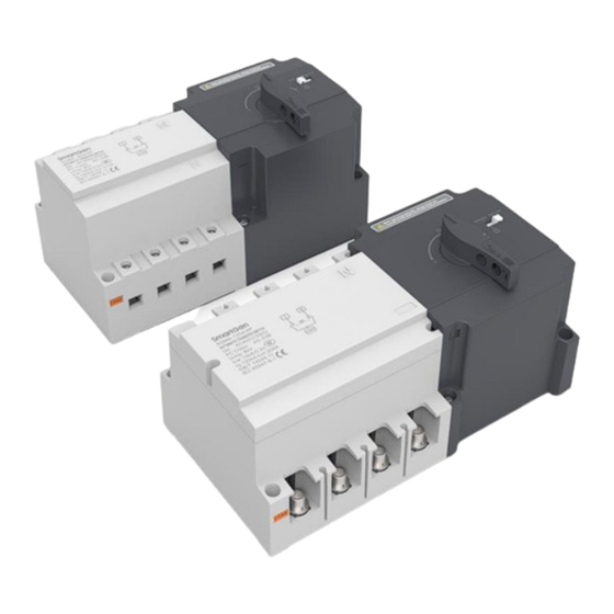
1 OVERVIEW SGM/SGMA63-630A series dual power ATS applies to the grounded power system of two neutral points, which requires AC400V 50/60Hz below, rated working current 16A~630A. Its structure is motor driven type, and there are three positions for the switch: normal (Ⅰ), spare (Ⅱ) and off (0). It can be used in the occasions where power failure is not allowed, such as high-rise buildings, medical heath, post and telecommunications, coal mine and ships, rail traffic, military and fire facilities. -
Page 5: Overall Dimensions And Category
3 OVERALL DIMENSIONS AND CATEGORY 3.1 INSTRUCTION SGM/SGMA63-630A series dual power ATS can be divided into two types according to their functions: genset type SGM series and ATS type SGMA series; while it can be divided into four types according to their shell frames: 80A/4P, 125A/4P, 250A/4P and 630A/4P. Three-pole and four-pole switches can be provided by each type, among which SGM-80/4P and SGMA-80/4P can also provide two-pole switch. -
Page 6: Sgm/Sgma Overall Dimensions And Technical Data
Shell Frame Classification 2-pole 3-pole 4-pole Model SGMA-80A 63A, 80A SGMA (ATS Type) SGMA-125A SGMA-250A None SGMA-630A 100A,125A,160A, 200A, 250A, 400A, 630A 3.2 SGM/SGMA OVERALL DIMENSIONS AND TECHNICAL DATA Fig.1 - SGM/SGMA-80A Shell Frame Page 6 of 13 SGM/SGMA63-630A Series Dual Power ATS User Manual... - Page 7 Fig.2 - SGM/SGMA-125A/250A/630A Shell Frame Table 4 SGM/SGMA Series Overall Dimensions Copper Dimensions Mounting Hole Size(mm) Busbar Hole (mm) Model (mm) A1 B1 H1 H2 P L L2 φ SGM-80A/4P 230 115 155 212 100 35 83 79 16.5 4 15.5 23 14 9 SGMA-80A/4P SGM-125A/4P 245 130 212 230 113 31 71 97.5 15.5 4.5 25 30 16 21.5...
- Page 8 SGM(A) SGM(A) SGM(A) SGM(A) SGM(A) SGM(A) SGM(A) SGM(A) SGM(A) Model -63A -80A -100A -125A -160A -200A -250A -400A -630A Withstand Current Rated SC Ability 17 kA 20 kA 30 kA 50 kA Rated Control AC230V Supply I-II or II-I Contact Trans. 0.6s±50% 0.6s±50% 1.0s±10%...
-
Page 9: Wirings
3.3 WIRINGS Fig.3 - SGM Series Terminal Table 6 SGM Series Terminal Description Sign Function Remark C1N I# Closed Control N-phase Input AC230V I# Closed Control I# Closed Control Control L-phase Input Terminal C2N II# Closed Control N-phase Input AC230V II# Closed Control II# Closed Control L-phase Input Closed Feedback COM... - Page 10 Fig.4 - SGMA Series Terminal Table 7 SGMA Series Terminal Description Sign Function Remark Common N-line Input Common N-phase input Open Control Input AC230V L-phase input Control Terminal II# Closed Control Input AC230V L-phase input I# Closed Control Input AC230V L-phase Closed Feedback COM Volts free feedback COM port Port...
-
Page 11: Working Condition
4 WORKING CONDITION Table 8 Working Condition Item Requirements Working Temperature (-25~+70)ºC Working Humidity (20~90)%RH Installation Height ≤2000m Pollution Degree 3-level 5 WIRING CONNECTION DIAGRAM 5.1 SGM (Genset) Fig.5 - SGM (Genset) Wiring Connection Page 11 of 13 SGM/SGMA63-630A Series Dual Power ATS User Manual... -
Page 12: Sgma(Ats)
5.2 SGMA(ATS) Fig.6 - SGMA (ATS) Wiring Connection 6 INSTALLATION AND DEBUGGING The installation and debugging of ATS should be carried out by professionals and person who knows the switchgear, the related protections and preventive measures must be considered during operating. -
Page 13: Ordering Model
7 ORDERING MODEL NOTE: The ordering models are based on the actual product models of SmartGen. Fig.7 - Ordering Model Table 9 Packing List Item Qty. Installation Instructions Arc-isolating Plate _________________________________ Page 13 of 13 SGM/SGMA63-630A Series Dual Power ATS User Manual...
Need help?
Do you have a question about the SGM63 Series and is the answer not in the manual?
Questions and answers