
Summary of Contents for Arise N180
- Page 1 USER GUIDE N180 N180 Web Guide Controller User Guide Technical Support:www.arisewebguiding.com Arise Technology...
-
Page 2: Safety Instructions
First of all, sincerely thank the masses of customers for choosing products of ARISE Technology (Chongqing) Co., LTD. In order to give full play to the performance of this equipment, please read this operation instruction before use. Please keep this manual in designated place, so that it’s easier review immediately when necessary. -
Page 3: Chapter 1. Product Introduction
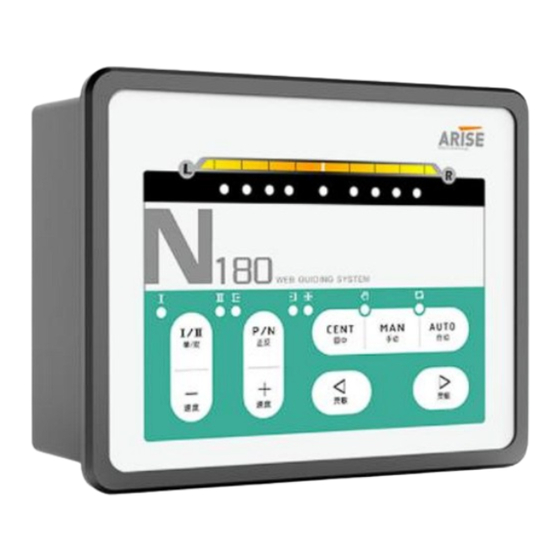
Chapter 1. Product Introduction N180 is a cost-effective web guide controller, which is specially used to track the edge of the material. It is suitable for automatic control of material rewinding, unwinding, and intermediate guidance. The N180 uses ultrasonic or infrared sensor to detect signals to calculate the deviation of the material, and according to the result, the stepping motor is driven to correct the offset material. -
Page 4: Chapter 2. Installation Environment And Wiring
USER GUIDE N180 Motor Speed PID dynamic programming Potentiometer adjustment analog Regulation algorithm circuit processing Or ordinary PID control Sensor interface Single/dual photoelectric eye Dedicated analog sensor analog、 Can't connect the switch sensor Ultrasonic sensor analog、 CCD sensor analog、 Can also be connected to two... - Page 5 USER GUIDE N180 2.2 Basic wiring The wire is connected before leaving the factory, and it can work normally by plugging in the corresponding plug directly. Under normal circumstances, do not remove the wire. If the wire needs to be lengthened, please record the wire...
- Page 6 USER GUIDE N180 "COM" or "right limit" and "COM" ", if the actuator stops, the short-circuited terminal is the upper limit input terminal in the corresponding direction, and the other end is the limit input terminal in the opposite direction.
-
Page 7: Chapter 3. Specification And Installation Size
USER GUIDE N180 Chapter 3. Specification and installation size 3.1 Standard specification Item Specification Working power input DC24V, electric current≥4A(Recommended 150W) Working power output DC12V, for sensor and limit switch, output Power supply current≤ Output control 0~24V , used to control... -
Page 8: Chapter 4. Operation Interface And Parameter Setting
USER GUIDE N180 Chapter 4. Operation interface and parameter setting LED Indicator Positive polarity Negative polarity Back to center indicator Double switch lamp Manual indicator Single switch lamp Auto indicator Single/double switch Auto Manual Polarity switch Back to center Speed decrease... - Page 9 USER GUIDE N180 mode. Left button: decrease sensitivity in auto mode. Inching control of motor in manual mode. I/II button: single or double switching value signal. P/N button: polarity switch. Arise Technology Technical Support:www.arisewebguiding.com...
- Page 10 USER GUIDE N180 Appendix Common faults and Solutions 1. There is no response after power-on, and all indicators are off Check whether the DC24V output of the power supply is normal, check whether the power cord is intact, whether the power plug is in good contact, and whether the wiring is correct, and then plug it in again.
- Page 11 USER GUIDE N180 the automatic state, and switch the sensor mode to the II mode. ⑤ The manual direction is reversed: you can reverse the A+ and A- lines, and at the same time reverse the left and right limit lines.
Need help?
Do you have a question about the N180 and is the answer not in the manual?
Questions and answers