Table of Contents
Advertisement
Quick Links
OWNER'S MANUAL
INSTALLATION INSTRUCTIONS
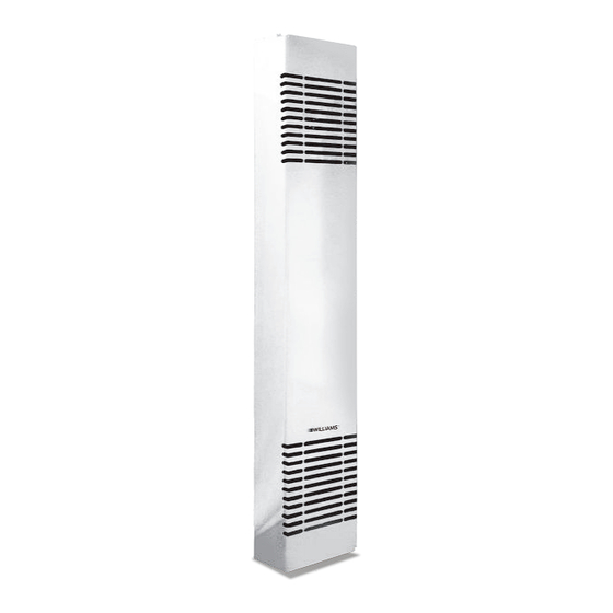
SOLANA
™
COUNTERFLOW FURNACE
MODEL NUMBERS:
3144030BG
3144030IG
3144030RG
3144030WG
SAVE THIS MANUAL FOR FUTURE REFERENCE.
READ THIS OWNER'S MANUAL CAREFULLY BEFORE YOU
INSTALL YOUR NEW WILLIAMS WALL FURNACE.
WARNING: This product can expose you to
chemicals including epichlorohydrin which is known to
the State of California to cause cancer and birth defects
and/or other reproductive harm. For information go to
www.p65warnings.ca.gov
WARNING: Improper installation, adjustment,
alteration, service or maintenance can cause injury or
property damage. Refer to this manual. For assistance or
for additional information consult a qualified installer or,
service agency.
250 West Laurel Street, Colton CA 92324
ELECTRIC
VISITE NUESTRA PÁGINA WEB PARA LA VERSIÓN EN ESPAÑOL DE ESTE MANUAL
www.williamscomfort.com
WARNING: If the information in these instructions
is not followed exactly, a fire or explosion may result
causing property damage, personal injury or loss of life.
- Do not store or use gasoline or other flammable vapors
and liquids in the vicinity of this or any other appliance.
- If you smell smoke:
DANGER OF ELECTRICAL SHOCK
• Do not touch heater.
• Immediately shutdown main electrical supply to heater.
• Extinguished any open flame.
• Contact a qualified installer or service agency.
•
www.williamscomfort.com
31,400 BTU/hr.
•
1-888-444-1212
Advertisement
Table of Contents

Related Manuals for Williams SOLANA 3144030BG


Summary of Contents for Williams SOLANA 3144030BG
- Page 1 3144030RG 3144030WG SAVE THIS MANUAL FOR FUTURE REFERENCE. READ THIS OWNER’S MANUAL CAREFULLY BEFORE YOU INSTALL YOUR NEW WILLIAMS WALL FURNACE. 31,400 BTU/hr. WARNING: This product can expose you to WARNING: If the information in these instructions chemicals including epichlorohydrin which is known to is not followed exactly, a fire or explosion may result...
-
Page 2: Your Williams Warranty
WARRANTY The manufacturer, Williams Furnace Co., warrants this wall furnace Some states do not allow limitation on how long an implied or heater to the original purchaser under the following conditions: warranty lasts, and some states do not allow the exclusion or... -
Page 3: Table Of Contents
CONTENTS YOUR WILLIAMS WARRANTY INSTALLATION RECORD TABLE OF CONTENTS SAFETY RULES INTRODUCTION BASIC TOOLS NEEDED BASIC MATERIALS NEEDED HELPFUL INSTALLATION INFORMATION OPTIONAL ACCESSORIES UNPACK YOUR FURNACE INSTALLING YOUR WALL FURNACE LOCATING WALL FURNACE AND THERMOSTAT INSTALLATION RECESSED MOUNT INSTALLATION SURFACE MOUNT INSTALLATION... -
Page 4: Safety Rules
SAFETY RULES 14. BE AWARE of good safety practices by wearing WARNING: Read these rules and the instructions personal protective equipment such as gloves and carefully. Failure to follow these rules and instructions safety glasses to avoid being injured by sharp metal could cause a malfunction of the furnace. -
Page 5: Introduction
INTRODUCTION Please read our instructions before you install and use your heater. This will help you obtain the full value from this HELPFUL INSTALLATION INFORMATION heater. It will also help you avoid any needless service costs The following booklets will help you in making the if the problem is something we cannot control and cannot installation: cover in our Warranty. -
Page 6: Unpack Your Furnace
INSTALLING YOUR FURNACE Locating Wall Heater The following steps are all needed for proper installation and Thermostat and safe operation of your heater. (sold separately) If you have any doubts as to any requirements, check with local authorities for local and state codes affecting Consider the following points before attempting to the installation. -
Page 7: Recessed Mount Installation
FIGURE 2 FIGURE 3 CUT WALL OPENING FLEXIBLE 4" CONDUIT 8" 71 1/2" 14 3/8" 75 1/2" WALL CUTOUT FOR 6" MIN. OPTIONAL REAR OUTLET CENTERED BETWEEN STUDS 12 1/4" 8 1/4" FINISHED FLOOR 4 3/4" FIGURE 4 ELECTRICAL ROUGH IN FINISHED FLOOR 0"... -
Page 8: Surface Mount Installation
INSTALLING YOUR FURNACE ELECTRICAL SUPPLY ROUGH IN FIGURE 5 CLOSE OFF STUD SPACE To properly route the conduit, electrical power supply wires and the thermostat wiring to heater top, you may make entry holes in the ceiling wall plate above 2 X 4 BACKING IF the heater. - Page 9 NOTE Flexible conduit may be used only if approved by your local codes and ordinances. If you have any doubt, consult your local Electrical or Building Inspector. The electrical supply wires, ground wire and the thermostat wires may now be routed to the heater location.
-
Page 10: Mounting Your Heater
MOUNTING YOUR HEATER NOTE FIGURE 7 HEATER MOUNTING If you are using the optional rear outlet, follow the METAL installation instructions on page 11 before proceeding. RECESSED MOUNT ANCHORS 1. If recessed mounted, clear recess of all debris. TOP FASTENING 2. -
Page 11: Installing Rearoutlet Accessory
INSTALL THE REAR OUTLET ACCESSORY FIGURE 8 - PLASTER GROUND POSITION RECESSED MOUNT HEATER Cut 8-¼ inch x 12-¼ inch hole in wall as shown in PLASTERGROUND Figure 3 on page 7. NAIL PLASTERGROUND TO WALL STUD Cut 8 inch x 12 inch opening in back of cabinet following scored lines stamped on the cabinet. -
Page 12: Electrical Connections
ELECTRICAL CONNECTIONS diagram on junction box cover plate and Figure 11. WARNING: When heater mounting has been completed, see steps 1, DANGER OF PROPERTY DAMAGE, 2 and 3 below. BODILY INJURY OR DEATH. TURN OFF ELECTRIC POWER AT FUSE BOX OR Refer to Figure 1, page 6. -
Page 13: Installing Your Trim Trim Strip Accessory 4701
INSTALLING YOUR TRIM STRIP ACCESSORY 4701 FIGURE 12 - TRIM STRIP TRIM STRIP ACCESSORY 4701 When desired, optional Trim Strip Kit may be used to cover the crack between heater and wall See Figure 12. Place strips tight against heater with other edge against TOP VIEW OF FURNACE wall surface and fasten to wall with escutcheon pins provided. -
Page 14: Operating Your Furnace
OPERATING YOUR HEATER The heater is controlled by means of 24 volt, wall-mounted WARNING thermostat. When the thermostat circuit is energized, DANGER OF BODILY INJURY OR DEATH low voltage relays are actuated which close circuits to the TURN OFF ELECTRIC POWER SUPPLY AT heating element and blower motor. -
Page 15: Wiring And Technical Information
WIRING AND TECHNICAL INFORMATION MODEL 3144030 TECHNICAL INFORMATION SPECIFICATIONS AND DIMENSIONS MOTOR AND FAN DATA ᴓ Model Voltage 240 1 Voltage 60 A.C. 60 A.C. HP (approx.) 1/40 RPM (approx.) 1,000 38.3 CFM (approx.) BTU/hr. 31,400 Width 14-1/8" CONTROL DATA Depth 7"... -
Page 16: Furnace Assembly Replacement Parts 300 Model
FURNACE ASSEMBLY REPLACEMENT PARTS 300 MODEL MODEL NUMBER Black 3144030BG Intergalactic 3144030IG 3144030RG White 3144030WG REF. REPLACEMENT PART DESCRIPTION 3144030BG 3144030IG 3144030RG 3144030WG Outer Casing 16C01BG 16C01IG 16C01RG 16C01WG Front Panel 16B10BG 16B10IG 16B10RG 16B10WG 16A07 16A07 16A07 Top Trim Cover 16A07 16A04 16A04... - Page 17 EXPLODED VIEW WITH PARTS...
-
Page 18: Service Record
SERVICE RECORD DATE MAINTENANCE PERFORMED COMPONENTS REQUIRED SOLANA ELECTRIC COUNTERFLOW FURNACE... -
Page 19: Hints And Information
2. Mfg. Date code / Serial Number 3. Part number 4. Part description All parts listed herein may be ordered from your equip- ment supplier. The model number of your Williams wall heater will be found on the name plate. - Page 20 www.williamscomfort.com | 888-444-1212 | 250 West Laurel Street, Colton CA 92324 USA Subject to change without notice | © 2024 P324031_RV_A 03/24...
Need help?
Do you have a question about the SOLANA 3144030BG and is the answer not in the manual?
Questions and answers