Table of Contents
Advertisement
Quick Links
Effective with serial No. IR24xxyyyy & following.
Nasarc Technologies, Inc.
602 Colby Drive
Waterloo, Ontario, N2V 1A2
Tel: (519) 747-0336, Fax: (519) 886-9022
WWW.NASARC.COM
INTELLIREAM
OWNER'S MANUAL
®
IOL
Safety Depends on You
DO NOT INSTALL, OPERATE, OR REPAIR
THIS EQUIPMENT WITHOUT READING THIS
MANUAL AND THE SAFETY PRECAUTIONS
CONTAINED THROUGHOUT.
ELECTRIC
LINCOLN
®
MULTI-WELD 350
ELECTR IC
MULTI-WELD 350
LINCOLN
®
U.S. Patent No.: 7,952,052
January 2024
IR-IOLOM-1
Advertisement
Table of Contents

Summary of Contents for Nasarc INTELLIREAM IOL
- Page 1 ® MULTI-WELD 350 ELECTR IC MULTI-WELD 350 LINCOLN ® OWNER’S MANUAL Effective with serial No. IR24xxyyyy & following. U.S. Patent No.: 7,952,052 Nasarc Technologies, Inc. 602 Colby Drive Waterloo, Ontario, N2V 1A2 Tel: (519) 747-0336, Fax: (519) 886-9022 WWW.NASARC.COM IR-IOLOM-1...
- Page 2 IR-IOLOM-1 DRAFT COPY...
- Page 3 Safety Information ® Before installation and commissioning of the INTELLIREAM IOL, please read and understand all of the following safety information. Failure to follow these instructions may result in damage to the equipment or personal injury. ® The INTELLIREAM IOL is constructed to be safe to operate provided: •...
- Page 4 Safety Information Moving parts can crush and cut. Keep hands away from the operating area of the reaming bit, clamp, and wire cutter. Rotating Cutter. Keep hands away from the operating area of the cutter. Entanglement Hazard. Do not operate with exposed long hair, jewelry, or loose clothing. Disconnect power before servicing.
-
Page 5: Table Of Contents
® INTELLIREAM Table of Contents Specifications ............................. 6 Installation ..............................7 2.1. Air Connection ............................. 7 2.2. Electrical Connection ........................... 8 Operation ..............................9 3.1. User Interface ............................9 3.2. Power-Up ............................9 3.3. Manual Operation ..........................10 3.4. IO-Link Specification and Data Map ....................11 Reamer .............................. -
Page 6: Specifications
® INTELLIREAM 1. Specifications PNEUMATIC SPECIFICATIONS Pressure: 80 PSI Flow: 16.5 SCFM Caution: Use Filtered (5um), Non-Lubricated, Regulated Air ELECTRICAL SPECIFICATIONS Voltage: 24 VDC +/- 10% Current: 0.75 Amp DC REAMING SPECIFICATIONS Speed: 1100 RPM Power: 0.60 HP WIRE CUTTING SPECIFICATIONS Minimum wire diameter: 0.030”... -
Page 7: Installation
® INTELLIREAM 2. Installation Danger of accident when connecting the pneumatic or electrical supply! - Prior to installation ensure that all protective measures have been taken and will remain in place while performing the installation. ® - Ensure that the air supply and electrical power to the INTELLIREAM IOL are disconnected until the installation is complete. -
Page 8: Electrical Connection
® INTELLIREAM 2.2. Electrical Connection WARNING: Damage to equipment may occur if connected improperly. Only a qualified technician should perform the following operation: ® Secure the connector into the receptacle at the side of the INTELLIREAM IOL, then connect the opposite side to a port on an IO-Link master. -
Page 9: Operation
® INTELLIREAM 3. Operation 3.1. User Interface The user interface is part of the Reamer Control Module (RCM-IOL) and can be found on the electrical supply ® side of the INTELLIREAM IOL (opposite the reservoir). The user interface provides the following features: •... -
Page 10: Manual Operation
® INTELLIREAM Start Lock: The start lock feature is a safety measure that blocks a command signal during power-up when it ® is unsafe to begin an operation. If a command is present while the INTELLIREAM IOL powers up or after an IOL will enter a start lock mode instead of cycling immediately and the “Error”... -
Page 11: Io-Link Specification And Data Map
® INTELLIREAM 3.4. IO-Link Specification and Data Map ® The INTELLIREAM IOL must be connected to an IO-Link master for full functionality. IO-Link Specifications M12 pinout Data transmission rate COM2 (38.4 kBaud) Minimal cycle time 10ms IO-Link Version IO-Link port type Class A Vendor ID 1842... - Page 12 ® INTELLIREAM IO-Link Process Data In (Device to Master) Address Name # Bits Data Values Notes Clamp is open, lift is retracted, motion enable is active, solenoid power is available [0].0 Ready 0 - 1 unit is not in remote mode, local lockout or start lock A cycle error has occurred, see Error Code [0].1 Error...
-
Page 13: Reamer
® INTELLIREAM 4. Reamer 4.1. Automatic Operation The following diagram shows the 7-step reaming sequence and color of the device status LEDs at each stage. The LEDs show the position of the clamp and lift cylinders on the control module. Clamp Raising Ream Bit... -
Page 14: Status Light
® INTELLIREAM 4.2. Status Light ® The status light on the top lid of the INTELLIREAM IOL indicates the current state of operation. Color Meaning Ready to cycle. In cycle or manual operation. Blinking 0-9 times In alarm, flashing error code (2-9). “Find Me”... -
Page 15: Reaming Bit Replacement
® INTELLIREAM 4.4. Reaming Bit Replacement • Disconnect air and electrical supply. • Remove the front ream guard cover (not shown). • Hold the ream rod, item 2, from rotating with a 5/8” wrench. • Unfasten the reaming bit, item 1, with a second 5/8” wrench. -
Page 16: Sprayer
® INTELLIREAM 5. Sprayer The sprayer may use a built-in post flow timer of 0, ¼, ½, or 1 second. Airflow from the spray nozzle will be present for the post flow time after the spray output and corresponding fluid valve have been turned off. -
Page 17: Spray Nozzle Replacement
® INTELLIREAM 5.3. Spray Nozzle Replacement • Disconnect air and electrical supply. • Lift spray cone straight up to remove. • Unthread spray nozzle and lift straight up to remove. • Replace in reverse order. pg. 17... -
Page 18: Ream And Spray Sequence Flow Chart
® INTELLIREAM 6. Ream and Spray Sequence Flow Chart The following flow diagram shows the recommended procedure for the reaming and spraying sequences. (At any time) “Complete” input on “Error” input on Move to “Ream” position Error Pulse “Ream” output for 0.5 sec Wait for “Complete”... -
Page 19: Wire Cutter Option
® INTELLIREAM 7. Wire Cutter Option ® The INTELLIREAM IOL offers a wire cutter as a factory installed option (IRW010099-00). The wire cutter is used to remove the ball at the end of the wire created by the welding process. It will leave the welding wire with a tapered point at the end of the wire stick-out for improved arc starting. -
Page 20: Wire Cutter Sequence Flow Chart
® INTELLIREAM 7.2. Wire Cutter Sequence Flow Chart ® The wire cutter utilizes the clamping cylinder and sensor already present on every INTELLIREAM IOL. Following is the suggested wire cutting program logic. (At any time) “Complete” input on “Error” input on Inch wire for 0.5 sec Error Move to “Wire Cut”... -
Page 21: Nozzle Detect Sensor Option
® INTELLIREAM 8. Nozzle Detect Sensor Option ® The INTELLIREAM IOL offers a nozzle detect sensor as a factory installed option (IRE120099-02). The integrated nozzle detect sensor is used to validate that the nozzle remains on the torch after the reaming process is complete. -
Page 22: Nozzle Detect Sequence Flow Chart
® INTELLIREAM 8.2. Nozzle Detect Sequence Flow Chart The process for checking for nozzle presence is outlined in the diagram below. “Nozzle Detect” input off Move to “Nozzle Detect” position “Aux Sensor” input on Nozzle Detect operation complete Error pg. 22... -
Page 23: Nozzle Gas Flow Sensor (Ngfs) Option
® INTELLIREAM 9. Nozzle Gas Flow Sensor (NGFS) Option ® The INTELLIREAM IOL offers a nozzle gas flow sensor as a factory installed option (NAC40A) The integrated nozzle gas flow sensor measures gas flowing out the end of the torch nozzle. This method is advantageous to an inline flow sensor installed in the gas hose as there may be undetected leaks downstream. -
Page 24: Ngfs Robot Position And Sequence Flow Chart
® INTELLIREAM 9.3. NGFS Robot Position and Sequence Flow Chart To properly detect gas flow, the correct robot position must be programmed with the nozzle inserted into the cone of the sensor. An approach position is recommended as the first step followed by the target position inside the cone. -
Page 25: Settings
® INTELLIREAM Settings ® Several features may be set up to optimize performance of the INTELLIREAM IOL. To access the configuration menus, press and hold the settings button for the required time as shown below. The device status LEDs will change their color pattern to indicate the menu that is accessible at a specific time. Release the settings button when the color pattern for the desired configuration menu is shown. -
Page 26: Motor Test
® INTELLIREAM Mode configuration: A specific running mode can be configured by the following procedure. Follow the steps outlined above to access the mode configuration menu. Upon releasing the settings button, the LEDs will flash green on top and bottom. This is the first in the sequence of teachable configurations. Subsequent pressing and releasing of the settings button will sequence the following configurations in order of appearance. - Page 27 ® INTELLIREAM Motor Diagnostic Configurations: Off: This feature is disabled. On: This feature is enabled. Note: Running the motor diagnostic will disable the feature so that it can only be run once each time it is enabled. Motor Diagnostic Operation: Once the reset button is released, the unit will display the power-up sequence. Follow this procedure to test the air motor manually: LIFT function: Press and hold the “LIFT”...
-
Page 28: Preventative Maintenance
® INTELLIREAM Preventative Maintenance ® The INTELLIREAM IOL will require periodic maintenance to ensure a dependable service life. The following schedule is recommended. Shut off the air supply and disconnect the power cable before making adjustments. DAILY • Check the fluid level in spray reservoir. •... -
Page 29: Troubleshooting
® INTELLIREAM Troubleshooting Problem Possible Cause Solution No device status LEDs on -Power is off -Turn power on -Fuse is blown (controller cabinet) -Replace fuse -Reset button defective -Replace reset button -Circuit board defective -Replace circuit board Clamp/Motor/Lift/Cutter not -Insufficient air supply -Set to 80 PSI, 15 SCFM working -Air line cut, disconnected, or twisted... -
Page 30: Error Codes
® INTELLIREAM 12.1. Error Codes ® The INTELLIREAM IOL reports errors using the status light. When an error is reported, the status light flashes the code at a rate of 2 flashes per second. When an error occurs during the reaming process, the clamp opens, the lift retracts, and the diagnostic report is shown with the top sensor LED in red. -
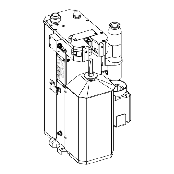
Page 31: Pneumatic Components
® INTELLIREAM Pneumatic Components The figure below shows the location for each pneumatic component. CLAMP CYLINDER FLUID SOLENOID SPRAY SOLENOID MANIFOLD ASSEMBLY CLAMP SOLENOID LIFT SOLENOID MOTOR SOLENOI PNEUMATIC INLET AIR MOTOR LIFT CYLINDER (other side) pg. 31... -
Page 32: Electrical Diagram
® INTELLIREAM Electrical Diagram pg. 32... -
Page 33: Replacement Parts List
® INTELLIREAM Replacement Parts List pg. 33... - Page 34 ® INTELLIREAM ITEM PART # DESCRIPTION IRE020099-09 STATUS LIGHT ASSEMBLY IRW010007-03 WIRE CUTTER GUARD (Optional) IRW010099-00 WIRE CUTTER ASSEMBLY (Optional) NAC40-2R NOZZLE GAS FLOW SENSOR replacement IRE020099-13 NOZZLE DETECT SENSOR replacement IRG010099-00 CLAMP ASSEMBLY IRE070099-07 RCM-IOL MODULE COMPLETE •IRE070008-00 RCM-IOL MEMBRANE •IRE090001-00 PC BOARD IOL IRE010012-00...
- Page 35 ® INTELLIREAM 14 A 14 B pg. 35...
- Page 36 ® INTELLIREAM ITEM PART # DESCRIPTION IRP010099-06 EXHAUST MUFFLER ASSEMBLY IRC010099-01 AIR MOTOR ASSEMBLY IRP020099-03 MANIFOLD ASSEMBLY •IRP020011-00 CYLINDER SOLENOID (2) •IRP020012-00 MOTOR SOLENOID IRP010006-00 BULKHEAD 5/16 IRS120099-03 FLUID RESEVOIR ASSEMBLY NST-5 32 oz WIDE MOUTH JAR IRS120010-00 SPRAY CONE PLUNGER IRP120099-02 MANIFOLD ASSEMBLY IRP120099-01...
-
Page 37: Warranty
NASARC. If a product warranty card has not been completed or proof of purchase is not available, the warranty will be deemed to become effective at the time the product leaves the factory authorized NASARC warehouse.
Need help?
Do you have a question about the INTELLIREAM IOL and is the answer not in the manual?
Questions and answers