
Related Manuals for Corsair iCUE ELITE LCD H100i


Summary of Contents for Corsair iCUE ELITE LCD H100i
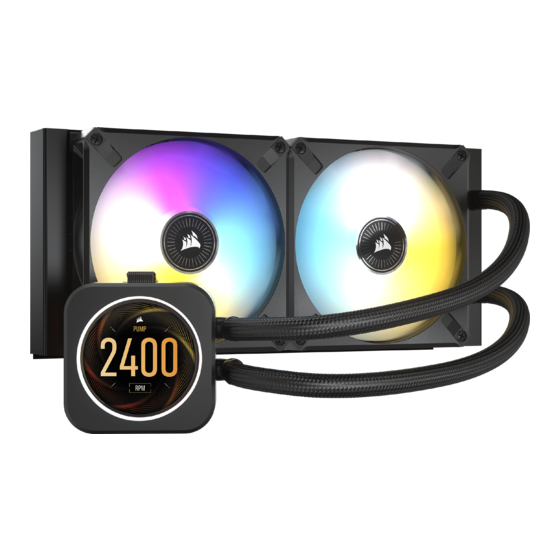
- Page 1 iCUE ELITE LCD H100i | H150i | H170i EXTREME PERFORMANCE LCD LIQUID CPU COOLER ENGLISH ITALIANO PУССКИЙ 简体中文 FRANÇAIS ESPAÑOL اﻟﻌﺮﺑﻴﺔ DEUTSCH PORTUGUÊS NEDERLANDS POLSKI...
-
Page 2: Installation
ENGLISH Note: Most newer PC cases include a CPU cut-out to allow access to the bottom of the motherboard. If your case does not include a cut-out, you will need to remove your motherboard from the case prior to installation. RGB Series coolers come with the Intel mounting bracket pre-installed on the pump for quick installation. -
Page 3: Included Hardware
INCLUDED HARDWARE Highlighted parts for Intel installation only x4 INTEL 1200/1150/1151/1156/1155 x4 INTEL 2011/2011-3/2066 STANDOFFS x4 INTEL 1700 STANDOFFS STANDOFFS x1 INTEL BACKPLATE x1 INTEL MOUNTING BRACKET x4 THUMBSCREWS (PRE-INSTALLED) x4 AMD AM4 STANDOFFS x4 AMD AM4 STANDOFFS x1 AMD AM4 MOUNTING BRACKET x1 AMD AM4 MOUNTING BRACKET x1 AMD STR4/STRX4 x1 AMD STR4/STRX4... - Page 4 1. Installing the Intel Backplate NOTE: Intel LGA 2011/2011-3/2066 do not require backplate installation. Proceed to step 2. 2. Installing the Intel Standoff Screws > Attach the provided Intel standoff for your socket. LGA 1200/1150/ 1151/1155/1156 > Use (A) for LGA 1200/115X, (B) for LGA 2011/ 2011-3/2066 or (C) for LGA1700.
- Page 5 3. Install the Fans and Radiator Attach the radiator and the fans as shown. For the best cooling performance, we recommend mounting the fans as an air-intake to your PC case. 4. Installing the Pump Unit > Align the bracket and pump over the standoff screws as shown.
- Page 6 INCLUDED HARDWARE Highlighted parts for AMD AM4 installation only x4 INTEL 1200/1150/1151/1156/1155 x4 INTEL 1200/1150/1151/1156/1155 x4 INTEL 2011/2011-3/2066 STANDOFFS x4 INTEL 2011/2011-3/2066 STANDOFFS x4 INTEL 1700 STANDOFFS x4 INTEL 1700 STANDOFFS STANDOFFS STANDOFFS x1 INTEL BACKPLATE x1 INTEL BACKPLATE x1 INTEL MOUNTING BRACKET x1 INTEL MOUNTING BRACKET x4 THUMBSCREWS (PRE-INSTALLED)
- Page 7 1. Installing the AMD AM4 Mounting Bracket > Remove the integrated Intel mounting bracket (figure 1). > Install the AMD AM4 bracket by pushing both sides into the slot on the pump until secure (figure 2). Note: It is important that the AMD AM4 retention bracket be evenly secured on all sides before installation.
- Page 8 4. Installing the AMD AM4 Standoff Screws > Attach the provided AMD AM4 standoffs to the CPU socket. > Tighten all four screws until firmly secure. 5. Installing the Pump Unit Align the bracket with the AMD AM4 standoffs as shown. Tighten the thumb screws until secure.
- Page 9 INCLUDED HARDWARE Highlighted parts for AMD sTRX4 installation only x4 INTEL 1200/1150/1151/1156/1155 x4 INTEL 1200/1150/1151/1156/1155 x4 INTEL 2011/2011-3/2066 STANDOFFS x4 INTEL 2011/2011-3/2066 STANDOFFS x4 INTEL 1700 STANDOFFS x4 INTEL 1700 STANDOFFS STANDOFFS STANDOFFS x1 INTEL BACKPLATE x1 INTEL BACKPLATE x1 INTEL MOUNTING BRACKET x1 INTEL MOUNTING BRACKET x4 THUMBSCREWS (PRE-INSTALLED)
- Page 10 1. Installing the AMD sTRX4 Mounting Bracket > Remove the integrated Intel mounting bracket (figure 1). > Install the AMD sTRX4 bracket by pushing both sides into the slot on the pump until secure (figure 2). Note: It is important that the AMD sTRX4 retention bracket be evenly secured on all sides before installation.
- Page 11 3. Install the Fans and Radiator Attach the radiator and the fans as shown. For the best cooling performance, we recommend mounting the fans as an air-intake to your PC case. 4. Installing the Pump Unit > Align the bracket and pump over the standoff screws as shown.
- Page 12 Connect Fans and Pump to Commander CORE > C onnect pump 24-pin cable to your Commander CORE (figure 1). > C onnect pump tach cable to the CPU_FAN header on your motherboard (figure 2). > C onnect each fan to the Commander CORE (figure 3). > C onnect each fan RGB lead to the Commander CORE (figure 3). 3-PIN FANS FANS figure 1 figure 2 figure 3 Connect Commander CORE and Elite LCD Module to USB 2.0 Header and Power > U sing the attached USB cable, connect the Commander CORE to a motherboard USB 2.0 header.
- Page 13 Ensure that the Commander CORE and LCD module are update to the most recent firmware via iCUE. If this does not resolve your problems, please open a ticket at support.corsair.com or contact our customer support team for further troubleshooting and assistance.
Need help?
Do you have a question about the iCUE ELITE LCD H100i and is the answer not in the manual?
Questions and answers