
Summary of Contents for Sepura SCU3 Series
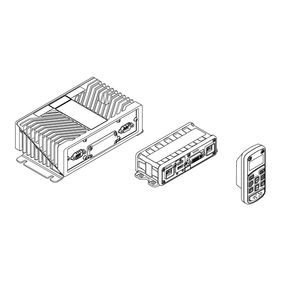
- Page 1 Mobile Broadband Control Unit Full Installation Guide SCU3 Series Control Unit SAH3 Series Accessory Hub...
- Page 2 Copyright © Sepura Limited 2022 All rights reserved. This document is intended for the use of Sepura Limited customers and/or other parties only for the purposes of the agreement or arrangement under which this document is submitted, and no part of it may be reproduced or transmitted in any form or means without the prior written permission of Sepura Limited.
-
Page 3: Table Of Contents
Contents Mounting the SCU3 and SAH3 ............ 13 Mounting the SCU3 ............13 Safety Information ................2 Mounting the SAH3 ............14 Unpacking ..................2 SCU3 and SAH3 Cabling and Connections ....... 14 SCU3 Model Variant Options ............2 DC Supply Connection ............14 Displays and Accessories ............. -
Page 4: Safety Information
A Sepura DVI-I Cable must be used for connecting the SCU3 to the SAH3. Displays and Accessories Sepura supplied microphones must be used. -
Page 5: Installation Precautions
If you do not understand the instructions, STOP and contact your service RF Energy provider or Sepura for assistance. Motor vehicle manufacturers make use of electronic vehicle control systems, Always read the vehicle manufacturer’s handbook before starting to install the e.g., ignition, anti-skid devices etc. -
Page 6: Installation Guidelines And Recommendations
Installation Guidelines and Recommendations Gas Powered Vehicles Before installation starts ensure that there are no gas leaks before This installation guide provides basic information about installing commencing an installation involving the use of electric tools as these can the products into land based vehicles (not marine based vehicles or produce sparks. -
Page 7: Temperature And Orientation Considerations
Temperature and Orientation Considerations Location Considerations The products must be fitted within the interior of the vehicle WARNING! The heatsink may become hot after long (excluding the engine compartment) and protected from the external periods of operation. Ensure accidental contact with environment and vehicle cleaning operations. -
Page 8: Connector Sealing
D-connector housings. DVI Connectors (SCU3/SAH3) CAUTION! To maintain an IP54 rating, only Sepura DVI interconnect leads must be used. 2. Insert the D-connector lead and 1. Fit the connector seals fully over all the fully tighten the thumbscrews. - Page 9 3. If any of the DVI connectors are unused, fit 4. Insert the USB bungs in any unused sockets. the DVI connector bungs and fully tighten the thumbscrews. USB Connectors (SCU3/SAH3) CAUTION! To maintain an IP54 rating, USB bungs must RJ45 Connectors (SCU3/SAH3/VCU) be fitted to any unused sockets and the USB face seal must be fitted to the SCU3.
-
Page 10: Important Sealing Information
4. Pull the boot forward over the connector ensuring the clip is engaged 3.5mm Jack Connector (SAH3) and the boot is fitted fully over onto the raised wall. 1. If the microphone socket is not used in the installation, insert the 3.5mm jack bung. -
Page 11: Rf Compatibility Checks
Parts Supplied RF Compatibility Checks On completion of the installation, the following checks must be The following items are supplied with the SCU3 and SAH3. carried out if the vehicle is equipped with electronic anti-skid, electronic ignition or engine management systems. Part no. -
Page 12: Scu3 Components And Connections
SCU3 Components and Connections Front Panel Rear Panel Component/Connector Type Description DC power input to the SCU3 with ignition sense (e.g. from a vehicle) Power I/O 15 Way D-sub, male and six GPIO lines Serial 9 Way D-sub, male Serial data connection Protective Cover See the section "Covered Panel"... -
Page 13: Covered Panel
Covered Panel Component/Connector Type and Description Micro USB sockets Diagnostic sockets - Not for customer use Reset Recessed button for resetting the SCU3 Power Recessed button for powering the SCU3 on and off Micro SIM 2 Secondary Micro SIM card slot - optional Micro SIM 1 Primary Micro SIM card slot Micro SD... -
Page 14: Vcu Components And Connections
VCU Components and Connections Fitting SIM or SD Cards Front Rear The SCU3 is fitted with slots to accommodate Mini or Micro SIM cards or a Micro SD card. The slots are concealed by the protective cover fitted to the from of the SCU3. CAUTION! Power OFF the SCU3 before fitting or removing SIM or SD cards. -
Page 15: Mounting The Scu3 And Sah3
Mounting the SCU3 and SAH3 2. Fit the mounting plate to the bottom of the SCU3 using the four screws supplied. CAUTION! Ensure fixing screws are of an appropriate type and length for the surface material the products are being mounted on to. IMPORTANT! Allow sufficient space around the products for cables and access to connectors. -
Page 16: Mounting The Sah3
SCU3 and SAH3 Cabling and Connections Mounting the SAH3 The SAH3 needs to be installed on a flat surface, typically concealed WARNING! DC supply leads, antenna cables and behind the dashboard or in a glove box compartment. speaker wiring must be routed as far away as possible from gas or fuel lines, and any in-vehicle electrical wiring. -
Page 17: Loudspeaker Connection
Microphone Connection 1. With the D connector ends of the power leads (SCU3 and SAH3) resting in their intended final positions, route the wires to a fused The SAH3 provides a standard 3.5mm jack socket for connection of a distribution box near to the vehicle battery, threading through the suitable microphone. -
Page 18: Usb Connections
3. Insert the microphone jack plug into the socket and rotate to either a To prevent accidental removal, the USB cables on the SCU3 and SAH3 top or side entry position. Secure the jack plug in position with a cable should be secured in place using the retention brackets available. - Page 19 3. Insert the USB connector into one of the sockets and route the cable SAH3 USB Retention through the retention clip, ensuring the minimum specified bend radius 1. Fit the retention bracket below the USB sockets in the correct is not exceeded. Secure the cable in position with a cable tie threaded orientation and secure with the screws and washers provided.
-
Page 20: Ethernet Connections
Sepura DVI Connector Dimensions CAUTION! Do not connect accessories such as a VCU IMPORTANT! When planning the installation, consider the dimensions of Sepura DVI connectors for or PTT to any of the Ethernet sockets. routing cables through bulkheads and conduits. -
Page 21: Digital I/O Connections
Digital I/O Connections Antenna Connections The SCU3 power lead provides connection wires for six I/O lines. WARNING! Observe all safety warnings relating to the If any of these I/O connection options are to be used, see the section location and use of the antennas. "Programmable I/O"... -
Page 22: Scu3 Cabling And Connections Overview
SCU3 Cabling and Connections Overview Wi-Fi/BT Antenna GNSS Antenna LTE Antenna MAIN MAIN SCU3 Front Panel USB Devices SCU3 Rear Panel Digital I/O Orange Input 1 Yellow Input 2 Ethernet Purple Input 3 Brown/White Input 4 / Output 1 Display 2 Green/White (optional) Input 5 / Output 2... -
Page 23: Sah3 Cabling And Connections Overview
SAH3 Cabling and Connections Overview SCU3 Power Supply USB Devices PTT / Power RED +VE SCU3 Installation button 12/24 Location BLACK -VE GREY/ BLACK GREY SAH3 Front Loudspeaker Panel Mouse Display 1 Microphone Ethernet SAH3 Rear Panel Main Interconnecting Cables SCU3 Power Cable + GPIO 5-30002 SCU3-SAH3 DVI Interconnect... -
Page 24: Programmable I/O
Open an automated gate or barrier • VOL max = 200mV @ 0.5A For details of how to program the functions refer to the Sepura DM documentation. For details of the signals and their characteristics, see the table in the next section. -
Page 25: Microphone And Ptt Installation
Microphone and PTT Installation 1. Insert the connector into the socket on the rear of the VCU, ensuring it clicks into position. It is recommended that the microphone is located away from any wind 2. Pull the boot forward over the connector noise in a position suitable for the user, such as near the internal rear ensuring the clip is engaged and the boot is view mirror. - Page 26 2. Fit the other half of the bracket into position AMPS Ball Mount on a suitable surface using four screws. The optional ball mount provides flexible mounting options for the VCU when used in conjunction with the range of compatible mounting arms and brackets.
-
Page 27: Powering On/Off
Powering On/Off SCU3 LED Indicator Depending on the installation, the SCU3 can be powered on by: The red LED on the front panel indicates the current status of the SCU3: • Turning on the vehicle's ignition LED Status Type • Pressing the Power button on the connected VCU or PTT Switch The SCU3 is off and cannot be powered on. -
Page 28: Scu3 Basic Configuration
1. Ensure the SCU3 is powered on and Android has booted up and is conversion cable/adapter) available for use on the connected display. • 720p (1280×720), 16:9 2. Tap to select Settings > Sepura Settings. • 800p (1280×800), 16:10 Accepted input signal 3. Make the required configuration changes: resolution •... -
Page 29: Technical Information
Technical Information Physical Data SCU3: Dimensions: ........180mm x 55mm x 108mm SAH3: Dimensions: ......... 147mm x 37mm x 59mm Electrical Data Voltage Input (SCU3/SAH3) Input Voltage Range: ..........6.0 - 36.0V DC Nominal Input Voltage (12V Vehicle) ......13.8V DC Nominal Input Voltage (24V Vehicle) ...... - Page 30 Sepura Limited 9000 Cambridge Research Park Beach Drive, Waterbeach CAMBRIDGE CB25 9TL. UK. T: +44 (0)1223 876000 www.sepura.com SPR-DOC-04539 Issue 1...
Need help?
Do you have a question about the SCU3 Series and is the answer not in the manual?
Questions and answers
VCU NOT NOT FULLY CONFIGURED WITH SAH3
No, the Sepura SCU3 Series VCU is not fully configured with SAH3 by default. The VCU must be connected to the SAH3 using an Ethernet cable, and proper mounting, cabling, and sealing procedures must be followed for installation and configuration.
This answer is automatically generated