
Subscribe to Our Youtube Channel
Summary of Contents for Advanced micro peripherals VAC2000
- Page 1 VAC2000 PC/104-Plus Video Annotation Controller board Document version: A.02 HARDWARE REFERENCE MANUAL...
- Page 2 Definitions AMP and Advanced Micro Peripherals are the trading names for Advanced Micro Peripherals Inc. and Advanced Micro Peripherals Ltd. Disclaimer This document contains information on a new product. Specifications and information herein are subject to change without notice. AMP reserves the right to make changes to any products herein to improve functioning and design. Although the information in this document has been carefully reviewed and is believed to be reliable, AMP does not assume any liability arising out of the application or use of any product or circuit described herein.
-
Page 3: Table Of Contents
VAC2000 Hardware reference manual Contents Introduction ..................... 4 Features ................................5 VAC2000 ‘at a glance’ ............................6 Technical specification ............................. 7 Functional summary............................8 Ordering information ............................10 Anti-static handling............................10 RoHS compliance ............................10 Installation ..................... 11 System requirements ............................11 Jumpers and connectors .......................... -
Page 4: Introduction
NTSC/PAL TV decoder, digital NTSC/PAL TV encoder, and video overlay controller. The VAC2000 accepts live NTSC or PAL analog video from a variety of sources including video cameras, digital video recorders or broadcast equipment. It can combine video with graphics or, video with video and provide output to drive a VGA monitor, TV monitor or TMDS flat panel display. -
Page 5: Features
1: Introduction VAC2000 Hardware reference manual Features NTSC/PAL input Live video input from NTSC or PAL composite or S-Video. (TV-decoder): Input from camcorder, video camera, VCR and broadcast signals. Full NTSC and PAL resolution. Software-controlled 4-input (composite) or 2-input (s- video) video source selection. -
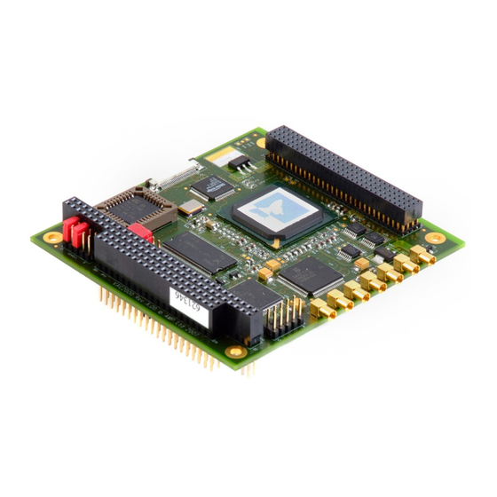
Page 6: Vac2000 'At A Glance
1: Introduction VAC2000 Hardware reference manual VAC2000 ‘at a glance’ Jumpers for IDSEL card and Flat panel TMDS output PC/104-Plus PCI card interrupt selection Jumpers for board configuration Analog VGA output Composite video/s-video input / output signals 16-bit PC/104 connectors ©... -
Page 7: Technical Specification
1: Introduction VAC2000 Hardware reference manual Technical specification Video input: Composite or S-Video monochrome, NTSC or PAL. Four software selectable video input sources. Software selectable brightness, contrast and saturation control. 1V peak-to-peak (75Ω termination). VGA display output: 640 x 480, 800 x 600, 1024 x 768 resolution as well as 720 x 480 (NTSC) and 720 x 576 (PAL). -
Page 8: Functional Summary
An input video multiplexer allows any one source to be selected under software control. Video inputs and outputs on the VAC2000 are provided on; low profile MMCX RF connectors for composite and S-Video, a 2 x 5 header for VGA output and a HIROSE 30 way flat-flex cable connector for flat panel TFT digital output (TMDS). - Page 9 VAC2000 Hardware reference manual Video overlay on text/graphics The VAC2000 allows the live video stream from the decoder to be overlaid as a rectangular window on top of, or blended with, text and graphics on the display screen. Internal hardware video and graphics acceleration ensures that the live video window can be scaled, repositioned and blended with minimal host CPU intervention.
-
Page 10: Ordering Information
The European RoHS Directive (Restriction on the use of certain Hazardous Substances – Directive 2002/95/EC) limits the amount of six specific substances within the composition of the product. The VAC2000 is RoHS-6 compliant. © 2009 Advanced Micro Peripherals Document version A.02... -
Page 11: Installation
IDSEL on the PC/104- Plus Plus bus. PC/104- with +5V logic tolerance. Windows, Linux or QNX (depending on VAC2000 SDK). Display devices VGA monitors – for annotation output. NTSC/PAL video monitors – for annotation outputs Video input NTSC/PAL camera or device with composite NTSC/PAL output. -
Page 12: Jumpers And Connectors
2: Installation VAC2000 Hardware reference manual Jumpers and connectors The following diagram shows the location of the jumpers and connectors available on the VAC2000: LEVEL TMDS PCI1 PROG1 AIN2 BIN2 TP10 TP11 AIN1 BIN1 © 2009 Advanced Micro Peripherals Document version A.02... - Page 13 S-Video input feed. Composite live video inputs The VAC2000 features two composite analog video inputs on Channel-A, either of which under software control, can be selected as the source for the live video overlay.
- Page 14 S-Video input feed. Composite live video inputs For the version of the VAC2000 supporting two live windows, a second live input channel is provided. Channel-B of the VAC2000 features two composite analog video inputs, any one of which under software control, can be selected as the source for the second live video overlay window.
- Page 15 CVBS out channel B (test only) Preview buffered incoming video signal. S-Video output The VAC2000 is available with an S-Video output containing mixed and overlaid text/graphics and live video information. The S-Video output can be obtained via MMCX connectors CHR and LUM. LUM: This is the Luminance output.
- Page 16 2: Installation VAC2000 Hardware reference manual VGA output VGA 2 x 5 header The following group of signals are designed for directly driving a PC VGA monitor. All the signals have corresponding (and adjacent) ground returns on VGA header, which should also go to the VGA monitor signal ground.
- Page 17 2: Installation VAC2000 Hardware reference manual Digital video output TMDS Hirose connector / DVI digital output The 30 way flex cable connector provides a method of attaching a TMDS/DVI display panel. With a 30-way flat flex cable fitted to TMDS, the pins (or strands)
- Page 18 System expansion buses PC/104 expansion bus JP12 and JP13 16-bit PC/104 bus I/F. The bus is only used for powering the VAC2000 card. The PC/104 bus is not used by the VAC2000 card. Bus pin-out is provided here for documentation purposes only.
- Page 19 2: Installation VAC2000 Hardware reference manual Row-A Row-B SA10 IRQ7 IRQ6 IRQ5 IRQ4 IRQ3 DACK2# BALE JP13 (PC104-CD) Row-C Row-D SBHE# MEMCS16# LA23 IOCS16# LA22 IRQ10 LA21 IRQ11 LA20 IRQ12 LA19 IRQ15 LA18 IRQ14 LA17 DACK0# MEMR# DRQ0 MEMW# DACK5#...
- Page 20 2: Installation VAC2000 Hardware reference manual Row-C Row-D SD10 DRQ6 SD11 DACK7# SD12 DRQ7 SD13 SD14 MASTER# SD15 (KEY) Plus PC/104- expansion bus PCI1 connector Row A Row B Row C Row D Reserved AD00 VI/O AD02 AD01 AD05 AD04...
- Page 21 2: Installation VAC2000 Hardware reference manual Row A Row B Row C Row D AD21 AD20 AD19 +3.3V AD23 AD22 +3.3V IDSEL0 IDSEL1 IDSEL2 AD24 C/BE3# VI/O IDSEL3 AD26 AD25 AD29 AD28 AD27 AD30 AD31 REQ0# REQ1# VI/0 REQ2# GNT0#...
- Page 22 The setting of the first two links on the LEVEL1 header determines the logical Plus stack position of the VAC2000 on the PC/104- stack. The setting on this header effectively routes the appropriate IDSEL, PCICLK, REQ and GNT signals to the VAC2000 Video Annotation Controller.
- Page 23 The setting of the 3 and 4 links on the LEVEL1 header determines which of the Plus 4 PCI Interrupts would service the VAC2000 card on the PC/104- stack. The following configurations are valid: Jumpers Pin 7-8 Pin 5-6 Interrupt...
- Page 24 2: Installation VAC2000 Hardware reference manual The following configurations are valid: Jumpers Pins Function Comment PAL_BOOT Removing this jumper will disable the TV output during POST If not fitted, the video controller must be AUTO_VGA enabled manually using I/O port writes...
-
Page 25: Installing The Card
2: Installation VAC2000 Hardware reference manual Installing the card Software for the VAC2000 is normally provided on CDROM supplied with the board at the time of purchase. Plus The VAC2000 should be fitted on the PC/104- stack. The optional VGA cable should be plugged into the 2 x 5 header labeled VGA. -
Page 26: Contacting Amp
/ embedded video experts available to provide a and free quick response to your technical queries. Please submit your technical support query to the appropriate email address: Technical support US Technical support UK E-mail: support@amp-usa.com E-mail: support@ampltd.com © 2009 Advanced Micro Peripherals Document version A.02...
Need help?
Do you have a question about the VAC2000 and is the answer not in the manual?
Questions and answers