
Summary of Contents for bravair FCL Series
- Page 1 Exposed Fan Coil Floor – Ceiling Unit FCL series Installation and Operation Manual Read this manual before using the fan coil Keep this manual for future reference...
-
Page 2: Table Of Contents
Table of Contents 1. Safety Information ..............2 1.1 Improper use ........................3 1.2 User and installer safety precautions ................3 1.3 Product precautions ......................4 2. Introduction ............... 5 2.1 Product Details ........................ 5 2.2 Specifications ........................6 2.3 Operating limits ......................8 2.4 Measurement ........................ -
Page 3: Safety Information
1. Safety information The Bravair Fan Coil units were manufactured in accordance with the latest technological standards and safety regulations. However, all fan coil units inevitably carry residual risks of injury to the user or damaging materials of the unit. For this reason, you should take note and follow all safety instructions. -
Page 4: Product Precautions
RISK OF INJURY DUE TO FAN ROTATION The rotating blades of the fan of the unit during its operation can cause injury. Before performing any operation to the unit, make sure that it is turned off and disconnected from power. RISK OF FALLING Wear special safety equipment such as gloves and helmet, especially when mounting the unit on a roof to avoid a possible accident of dropping the unit from... -
Page 5: Introduction
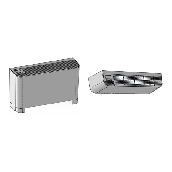
2. Introduction 2.1 Product Details Air grille Digital thermostat Exchanger: Copper tube DN 20 connections with φ9,52mm with female thread and hydrophilic drainage tubing aluminum sheets Air filter Mounting holes Drainage Pan Fan with galvanized steel sheet Long-lasting 3-speed motor... -
Page 6: Specifications
2.2 Technical Specifications Model FCL -030 FCL – 040 FCL - 060 FCL - 070 FCL – 080 Cooling Capacity (1) 1800 2700 3600 4500 5400 (Water Outlet 7°C) Heating Capacity (2) 1950 2750 3750 4650 6300 (Water Outlet 50°C) Heating Capacity (3) 3500 4800... - Page 7 Model FCL - 110 FCL - 140 FCL - 160 FCL -190 Cooling Capacity (1) 7200 9000 10800 12600 (Water Outlet 7°C) Heating Capacity (2) 8000 9800 11200 13000 (Water Outlet 50°C) Heating Capacity (3) 11600 14800 17700 19300 (Water Outlet 70°C) Air Supply 1360 1700...
-
Page 8: Operating Limits
2.3 Operating limits Maximum allowable working hydraulic pressure 1,6 MPa (16 bar) Maximum allowable water temperature 80 °C Minimum permissible water temperature 7 °C Maximum allowable ambient temperature 40 °C Minimum permissible ambient temperature 2 °C Operating voltage 220±10% 50Hz AC. Power consumption / protection class See product nameplate 2.4 Measurement... - Page 9 Mounting hole Foot Measurement FCL - 030 FCL – 040 FCL - 060 FCL - 070 FCL – 080 FCL - 110 FCL - 140 FCL - 160 FCL -190 (mm) 1100 1260 1450 1680 1880 2070 overall length 1130 1360 1560 1750...
-
Page 10: Wiring Diagram
2.6 Electrical diagram LCD THERMOSTAT N: NEUTRAL H: HIGH SPEED M: MEDIUM SPEED L: LOW SPEED ON: 3 WAY VALVE ON OFF: 3 WAY VALVE OFF L: PHASE Power Supply (220V) NOTE! Before making any wiring connection, consult the corresponding indicators on the thermostat. -
Page 11: Installation
3. Installation 3.1 Package Contents - Fan coil unit - User and installation manual - Connection piping (2 pcs) - Drain hose (1 pcs) - Support legs (optional) Wireless remote control (optional 3.2 Minimum installation distances 10 cm 4 cm 4 cm 10 cm 1. -
Page 12: Mounting A Unit
3.3 Mounting a unit o The supply and return pipes must be equipped with flexible spiral tubes and valves to control the flow of water and be easily accessible. o The condensate tube should be slightly lower than the drainage pan and should not have bends to ensure proper condensate runoff o If the fan coil needs to be operated in cooling, the water supply and return pipes and condensate pipe should be well insulated. -
Page 13: Pipe Connection
3.4 Pipe connection The next photo shows the connection of the supplies to the unit: OUTLET: System return INLET: System flow Return Flow Drain hose connection NOTE! Bleed the air from the fan coil by turning the bleeding valve counterclockwise. As soon as water comes out, tighten clockwise again. -
Page 14: Metal Frame Removal
3.5 Metal frame removal - Open the plastic caps at the corner right and left and unscrew the screws from the top. - Remove from the bottom of the fan coil the three necessary screws to release the frame. - Drag the unit’s frame out to remove it... -
Page 15: Hydraulic/Electrical Connection Of Two Or Three-Way Water Valve
3.6 Hydraulic/Electrical connection of two or three-way water valve The units are supplied without water cut-off valves. In case of installation of a two- way or three-way water valve, consult the connection diagram below. Two-way valve Three-way valve NOTE! The water inlet is at the lower supply while the outlet is at the upper one (see the sign next to the unit’s hydraulic connections). -
Page 16: Thermostat Operation
4. Thermostat operation 4.1 Technical parameters • • Temperature control accuracy: ±1°C Sensor: NTC Sensor • • Display: LCD Humidity: 5~45 RH • • Dimensions: 86*86*14 mm(W*H*L) Temperature configuration: 0/45°C 4.2 Thermostat interface explained Fan speed indicator Display of desired Display of desired temperature Room temperature... -
Page 17: Operating Instructions
4.3 Operating instructions ON/OFF: Press the button to turn on/off the unit. Temperature adjustment: Press the arrows ("▲" / "▼") to adjust the room temperature to an accuracy of 1°C. Operation: When active press the function button to switch, the display means cooling, the means heating, and no icon means that the unit is in ventilation mode. -
Page 18: Unit Configuration
4.4 Unit configuration When the unit is off, press and hold the function button and the fan speed button for five seconds to enter configuration, then briefly press the power key to navigate in the options and press "▲" and "▼" to configure. # Par. - Page 19 4. Restart from a power failure: Choose whether to restart the unit if it turns off due to a power failure. 00: No restart. 01: Restarts to factory settings. 02: Restarts and resumes to the previous operation. 5. Lower temperature limit value: With this parameter you can set the lower limit of the desired temperature.
-
Page 20: Maintenance
5. Maintenance 5.1 Precautions for use and maintenance 1. The temperature of the cold water supplied by the unit in summer should not be lower than 7°C and the temperature of hot water supplied in winter should not be higher than 80°C. The water source used should be softened, taking into account the quality of water in different places. - Page 21 Damage Cause Solve The desired temperature Increase the desired is lower than room temperature The fan does not work during temperature heating Check the temperature Water temperature is not and flow of water and sufficient also the value of parameter 10 The desired temperature The fan does not work during Reduce the desired...
- Page 24 Παράπλευρος Εγνατίας οδού, κόμβος Διαβατών Τηλ. 2310 574 920 – 2310 574 803 www.alkyon-hvac.gr...
Need help?
Do you have a question about the FCL Series and is the answer not in the manual?
Questions and answers