Advertisement
Quick Links
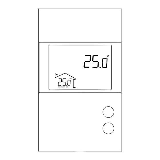
TRM-FH-Bronze
Installation Guide
Non-programmable floor
heating thermostat
Increasing or lowering the temperature
To adjust the temperature, press
or
. The requested temperature
will blink to confirm the new setpoint.
Placing the thermostat on standby
Press and hold the
and
buttons simultaneously for 3 seconds to place
the thermostat on standby. The LCD display will not be blank; the
will be displayed.
When the thermostat is on standby, press
or
thermostat. The thermostat will resume operation under its last program
settings.
A thermostat that is placed on standby before a power failure will be on
standby by default when power is restored.
USER SETTINGS
Get the setpoint to its minimum and hold the
button for 10 seconds to access the menu.
Press the
or
button to change
the setting.
Press the
and
buttons simultaneously
to save and go to the next parameter.
Continue to press until the end of the list to
exit the menu.
Alimentez le thermostat.
Warnings
The installation of this thermostat must be performed by a certified
electrician and comply with the national and local electrical codes
and regulations.
1
Unlock and lift the
thermostat cover.
3
Connect the 10 kohm floor
sensor as shown below:
USER SETTINGS
Name
Display
symbol
to turn back ON the
Backlight
Control
Setpoint Min
Setpoint Max
Limit Air Max
Limit Floor Max
Limit Floor Min
Sensor
10 sec.
Aux
INSTALL YOUR THERMOSTAT
2
Connect the heating cable(s)/mat(s) (Load) wiring and electrical
supply (Line) feed to the load / line wire connectors located on
the back of the thermostat. Connect the ground wire to the
screw in the electrical box intended for this purpose.
Load
Floor heating
Line
4
Use the supplied screws to
secure the thermostat to the
electrical junction box.
Replace the cover and lock.
Sensor
Parameters & settings
Display
Temperature format
°C or °F (default: °C)
Backlight control
ON or OFF (default: OFF)
Control mode
A (Air), F (Floor) (default: F)
Minimum setpoint
5 °C to 36 °C (default: 5 °C)
Maximum setpoint
5 °C to 36 °C (default: 36 °C)
Maximum ambient temperature
(Visible only in F mode)
5 °C to 36 °C (default: OFF)
Maximum floor temperature
(Visible only in A mode)
5 °C to 36 °C (default: OFF)
Minimum floor temperature
(Visible only in A mode)
5 °C to 36 °C (default: OFF)
Floor sensor
10K or 12K (default: 10K)
Assignment of auxiliary output
OFF, EXP, 15 sec, 15 min (default: OFF)
Before starting the installation of your new thermostat, make sure that the
breakers for your heating system are off at the main electrical panel!
The thermostat installer MUST ensure to
firmly secure all wiring connections prior
to installation of the thermostat in the
junction box; failure to properly connect
the thermostat wiring may lead to a site
hazard/liability being created.
5
Power up the thermostat.
After performing a test sequence, the
thermostat should display the floor
temperature. If not, refer to the
troubleshooting guide in
this manual.
3) The thermostat offers 2 temperature regulation modes:
F mode (default): Regulates the floor's temperature by means of an external
temperature sensor with the possibility to limit ambient temperature.
A mode: Regulates the ambient temperature with the possibility to limit floor
temperature by means of an external temperature sensor.
6) Maximum ambient temperature limit (F mode)
The thermostat limits floor heating to ensure that the ambient temperature does
not exceed the selected limit.
7) Maximum floor temperature limit (A mode)
The thermostat limits floor heating to the set temperature to ensure it does not
exceed the selected limit: ideal for protecting engineered wood floors.
10) Assigning the auxiliary output (F mode):
The thermostat provides an auxiliary output that has one function which is set
from the user settings.
EXP function: Auxiliary output to connect several heating floors
(Expansion unit sold separately)
Assigning the auxiliary output (A mode):
The thermostat provides an auxiliary output that has three functions which are set
from the user settings.
15 sec function: Short cycle auxiliary output (15 seconds): used for a heater
controlled through an electronic relay (SSR).
15 min function: Long cycle auxiliary output (15 minutes):
used for a heater controlled through an electromechanical relay or
equipped with a fan.
In the 15 sec and 15 min functions, the thermostat controls the ambient
temperature with the floor. Once the floor temperature has reached its limit, if
the desired ambient temperature is not reached, the auxiliary output activates
the heating device to reach the set temperature. (The auxiliary output acts as a
second heating stage.)
EXP function: Auxiliary output to connect several heating floors
(Expansion unit sold separately)
Advertisement

Summary of Contents for TRM TRM-FH-Bronze
- Page 1 Connect the heating cable(s)/mat(s) (Load) wiring and electrical thermostat cover. supply (Line) feed to the load / line wire connectors located on the back of the thermostat. Connect the ground wire to the TRM-FH-Bronze screw in the electrical box intended for this purpose. Installation Guide Load...
- Page 2 TRM shall in no case be liable to any party for any loss of profit, loss of was not caused by accident, misuse, neglect, alteration or improper...
Need help?
Do you have a question about the TRM-FH-Bronze and is the answer not in the manual?
Questions and answers