Table of Contents
Advertisement
Quick Links
Advertisement
Table of Contents

Summary of Contents for ON Control SUSA
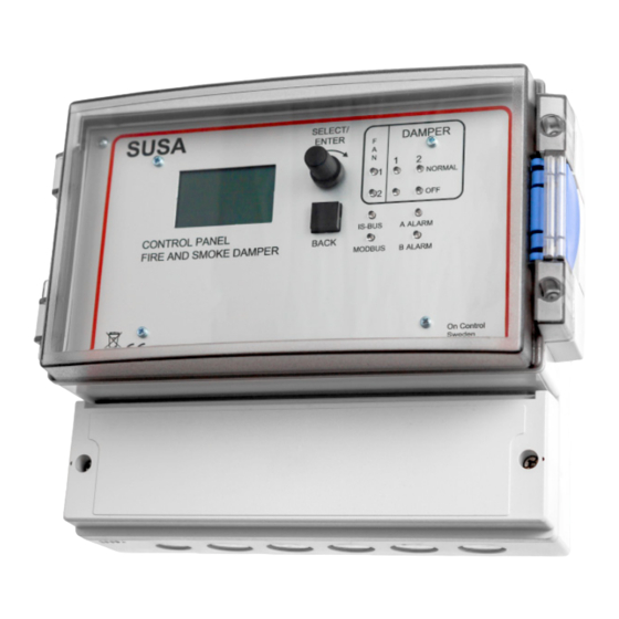
- Page 1 SUSA Control and monitoring unit MANUAL...
-
Page 2: Table Of Contents
Terminology ....................15 Operation/troubleshooting .................16 DESCRIPTION The SUSA is a control and monitoring unit designed to control various types of fire/smoke dampers and fans in a flexible way. FW 3.0 and later is not compatible with the older expansion unit SUSB. -
Page 3: General System Overview
GENERAL SYSTEM OVERVIEW The following diagram is a typical example of network mode between the SUSA master unit and slave units. KBOX replaces the required connection point between the motor and the control panel. It has no functional requirements and makes installation much easier. There is always one KBOX for each damper. -
Page 4: Connections
CONNECTIONS Central fire alarm/night mode (normally jumpered) A ALARM DET2 Smoke Damper connection group 1 detector loop 2 Damper connection group 2 DET1 Smoke detector loop 1 Power supply MODBUS G0 M G0 M 10 11 12 13 14 15 16 17 18 230V/50Hz 19 20 21 22 23 24 25 26 27 28 29 30 31 32 33 34 35 36 Gnd A B... -
Page 5: Damper Wiring
DAMPER WIRING Wiring - INDIVIDUAL Wiring - PARALLEL 10 11 12 13 14 15 16 17 18 10 11 12 13 14 15 16 17 18 27 28 29 30 31 32 33 34 35 36 19 20 21 22 23 24 25 26 27 28 29 30 31 32 33 34 35 36 G0 M S Ö... -
Page 6: Wiring With Kbox
WIRING WITH KBOX You are recommended to use the KBOX connection box for easier wiring of 24 V fail-safe motors with spring return. The connection box also simplifies parallel connection and troubleshooting. See the drawing below. Wiring - INDIVIDUAL One damper per damper group. NOTE! Leave the jumpers in position... -
Page 7: Inputs
The network is terminated at the start and end. The termination consist of a jumper on the PCB. In Function test the SUSA it is called UA2 and is located to the left of Choose "Manual tests" and the test type. Dampers terminal number 1. -
Page 8: First Startup
FIRST STARTUP When you switch on the SUSA for the first time, there are some settings menus you need to work through before it can be used. All the individual menus are described in the settings and only a few changes need to be made. -
Page 9: During Startup
KSUB, at least 2.0 for a KSUE and at least 3.2 You can now activate the inputs used in the slave units by for a KSUC in order to work with the SUSA. The specifying the damper type and function group. - Page 10 The fire ventilation fans can be controlled from one or two outputs on the SUSA. If two fans are connected, they are started with a 15 second interval if a detector is triggered.
-
Page 11: Menu System
MENU SYSTEM A detailed description is provided for the menus that INFO are not self-explanatory. The navigation structure is presented below. Login Info log You must log in in order to configure the system. The Test log password is AAAA. You can change the password in a Alarm reset submenu. - Page 12 MENU SYSTEM MENU DESCRIPTION INFO MENU Status: OK The status indicates whether the system is alarm free and provides brief status Sun 21-05-23 17:59:07 ------------------------- information. Status:OK Status: OK? means that the dampers are in an undefined position, e.g. during damper Normal mode opening.
- Page 13 LED alarm. The alarm will not completely disappear until the alarm has been reset in the SUSA and the fault has been corrected in the installation. The on/off LED indicates that the alarm panel has a power supply, not that it is activated. Up to three alarm panels can be connected.
-
Page 14: Specification
SPECIFICATION Attachment Inputs Intended to be attached to a wall indoors. Smoke detector 1. Terminals 4-5. Smoke detector 2. Terminals 6-7. Power supply PRES. Terminals 28-29. Pressure switch from smoke 230 VAC, 50 Hz, 30 VA. Fused with max 10 A / min 2 A. extraction fan. -
Page 15: Terminology
Damper tests (if any) can take place at this time. Function groups The SUSA consists of two halves called function groups. Each group has dampers, detectors and fan relays. All dampers and detectors must be assigned to one or both groups. The groups themselves have various group functions which can be set in the "Group config."... -
Page 16: Operation/Troubleshooting
Check that the dampers indicate the position OFF or CLOSED in the unit(s) where they are installed. Check that slave units are correctly connected and addressed. Check that the dampers are configured in the SUSA. B FAN The two fan controls are indicated with separate LEDs which light up when the relevant relay is closed. - Page 17 The green LED flashes when a correct message is received from a slave unit. MODBUS The green LED flashes when a correct message is received from the Modbus master (SCADA). This confirms that the communication parameters and checksum are correct when the message is received by the SUSA. MANUAL 17 / 18...
- Page 18 PROFCON AB Victor Hasselblads gata 9 421 31 Västra Frölunda Sweden Tel: +46 (0)33 25 65 70 Web: oncontrol.se On Control is a registered trade mark of PROFCON AB MANUAL v2.01 18 / 18...
Need help?
Do you have a question about the SUSA and is the answer not in the manual?
Questions and answers