Table of Contents
Advertisement
Quick Links
Model: D6
2D LiDAR
USER MANUAL
QUICK START
Turn on the external power supply +5V ± 10%, 2A
(starting current requirement is greater than 1.5A),
Connect the device to the computer via a USB cable,
By setting the alarm area need to be protected,
To start the early warning of the intrusion behavior of the designated area.
(Version V8.01.2)
For more info & supports, please visit http://www.top1sensor.com
Advertisement
Table of Contents

Summary of Contents for Faselase D6
- Page 1 Model: D6 2D LiDAR USER MANUAL QUICK START Turn on the external power supply +5V ± 10%, 2A (starting current requirement is greater than 1.5A), Connect the device to the computer via a USB cable, By setting the alarm area need to be protected, To start the early warning of the intrusion behavior of the designated area.
-
Page 2: Table Of Contents
Contents 1. Specifications ..................... - 1 - 2. Dimensional drawing ................- 1 - 2.1 Lidar pictures ..................- 1 - 2.2 Dimensional drawing ................- 2 - 3. Operating mode ..................- 2 - 3.1 Fixed device ........................- 2 - 3.2 Connection ........................ -
Page 3: Specifications
2D Lidar Specifications Items Parameters Distance measuring range 0.15m~6m@10% 360° Scanning angle range 10Hz Scanning frequency 3*NPN OUT, 2*NPN IN; Output interface TTL to USB setting interface 921600bps Communication baud rate Laser diode 905nm, ≤1mW; comply with GB7247.1-2001 Laser source Class 1 Laser Eye Safety Requirements Power supply DC5V±... -
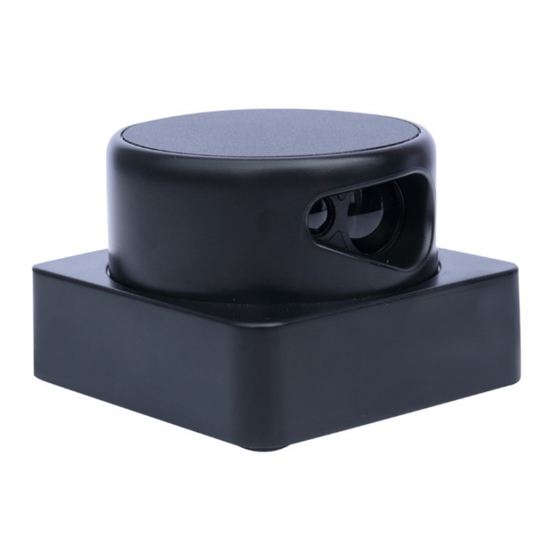
Page 4: Dimensional Drawing
2D Lidar 2.2 Dimensional drawing 3. Operating mode 3.1 Fixed device The above image is an upward view of the device, using four M3× 10 self-tapping screws. - 2 -... -
Page 5: Connection
2D Lidar 3.2 Connection 3.2.1 Wiring diagram 3.2.2 Definitions of 10pin connection wire Function Color Notes Positive pole of DC power supply +5V +5V±10% White DC power ground Yellow Connect to external TTL Rx Green Connect to external TTL Tx Black Connect to internal GND White... -
Page 6: Power Supply
The starting voltage need to be 5V, the starting current need to be 1500mA, the normal working current is 500mA. However the ripple coefficient of the power supply should not be greater than 40mV.The factory setting is that the D6 automatically starts rotating after power-on. Software setting 4.1 Driver running... -
Page 7: Protection Range Setting
Baud rate: 921600 bps , Parity bit: None , Data bits: 8 , Stop bit: 1 D6 outputs real-time point cloud data or switching amount signal, Only the change in the switching amount status can be seen through the software. - Page 8 2D Lidar ①Set the required level state of each IO_IN when setting the input group. ②Select the input group to be set through the drop-down menu. ③The total number of areas of the current group and the total number of areas of all groups. ④The group where the current Lidar internal scanning detection is located.
- Page 9 2D Lidar high and low level can make the IO output port state reverse. The protection area can be set as a sector or polygon, the coordinates in the settings are in centimeters. The Lidar starts detecting obstacles in the area. The font in the area where obstacles are detected changes from green to red, and the I/O output port level changes at the same time.
-
Page 10: Standard And Optional Accessories
After all settings are completed, click Save selected area or Save all to device and then click Run, the Lidar starts working according to the newly set area. 5. Standard and optional accessories Items Qty(pc) Remarks D6 Lidar Data cable TTL to USB adapter plate DC +5V power adapter - 8 -... -
Page 11: Contact Us
2D Lidar 6. Contact us Xi’an Zhizun International Trade Co., Ltd. Http://www.top1sensor.com Tel: +86-29-87858956 Fax: +86-29-87858956 Mobi: +86-13201520716 Mr. Yang E-mail: contact@top1sensor.com Add: No.68 Middle Sector South,Huancheng Road,Xi'an,China - 9 -...
Need help?
Do you have a question about the D6 and is the answer not in the manual?
Questions and answers