
Subscribe to Our Youtube Channel
Related Manuals for Titus FMS-2000M

Summary of Contents for Titus FMS-2000M
- Page 1 FMS-2000M CRITICAL ENVIRONMENT MONITOR INSTALLATION GUIDE Redefine your comfort zone. | www.titus-hvac.com...
-
Page 2: Installation Checklist
INSTALLATION CHECKLIST RISK OF ELECTRIC SHOCK Do not install or use this FMS-2000M Critical Environment Monitor in or near environments where corrosive substances Disconnect the power supply before making electrical or vapors could be present. Exposure of the FMS-2000M connections. Contact with components carrying hazardous... - Page 3 Le non-respect de cette précaution peut Important protégé par un disjoncteur d’un minimum de 20 A. Placez amener un fonctionnement anormal après redémarrage de le disjoncteur du FMS-2000M dans un panneau électrique l’équipement. approuvé et situé à l’écart, mais à proximité. www.titus-hvac.com...
-
Page 4: Table Of Contents
FERRITE INSTALLATION INSTRUCTIONS FOR FMS-2000M SERIES ........7 INSTALLING THE FMS-2000M THIN MOUNT DISPLAY FOR A RETROFIT APPLICATION ......9 INSTALLING THE FMS-2000M THIN MOUNT DISPLAY FOR A NEW APPLICATION . -
Page 5: Introduction
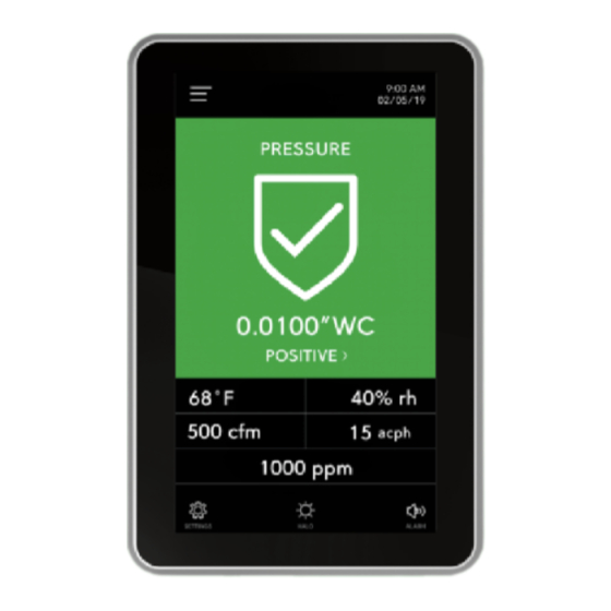
0.0001 in. W.C. or 0.0249 Pa and display measurements on a 5 in. (12.7 cm) diagonal touch screen. The FMS-2000M provides maximum room status awareness with the color coded visual alarms that display on screen, and the 360° Safety Halo illuminated edge which you can use to easily monitor spaces down long corridors. -
Page 6: Location Considerations
LOCATION CONSIDERATIONS Install the FMS-2000M monitor directly outside the monitored space, at the nurses’ station, in the engineering office, or at any other location that you need. Place the sensors away from any moving air source such as ceiling air registers, because this can cause unstable sensor behavior. -
Page 7: Ferrite Installation Instructions For Fms-2000M Series
FERRITE INSTALLATION INSTRUCTIONS FOR FMS-2000M SERIES To provide FCC and CE compliance for the FMS-2000M critical environment monitor and its application, use the cable ferrites that are included in the package for the installation as described. Install the three cable ferrites included on the AC input cable to the isolated power supply module, and on the wires that supply 24 VAC power to the pressure sensor module. - Page 8 FERRITE INSTALLATION INSTRUCTIONS FOR FMS-2000M SERIES TABLE 2: FMS-2000M CRITICAL ENVIRONMENT MONITOR COMPONENTS Callout Component FMS-2000M monitor Supplied remote pressure sensors 1, 2, 3, and 4, in order from left to right Optional door switch Note: Configure the door switch setting on the monitor. It can be normally closed or normally open.
-
Page 9: Installing The Fms-2000M Thin Mount Display For A Retrofit Application
1/16 in. hex wrench to drive the screw into the monitor until it engages with the tab. After you mount the FMS-2000M monitor, apply power to the monitor. The initial splash screen displays the Titus logo and the Safety Halo bezel lights up green to represent the current system status. - Page 10 INSTALLING THE FMS-2000M THIN MOUNT DISPLAY FOR A RETROFIT APPLICATION FIGURE 5: FMS-2000M CRITICAL ENVIRONMENT MONITOR COMPONENTS FOR A RETROFIT APPLICATION TABLE 3: FMS-2000M CRITICAL ENVIRONMENT MONITOR COMPONENTS FOR A RETROFIT APPLICATION Callout Component FMS-2000M Critical Environment Monitor Monitor Bracket...
-
Page 11: Installing The Fms-2000M Thin Mount Display For A New Application
After you mount the FMS-2000M monitor, apply power to the monitor. The initial splash screen displays the Titus logo and the Safety Halo bezel lights up green to represent the current system status. - Page 12 INSTALLING THE FMS-2000M THIN MOUNT DISPLAY FOR A NEW APPLICATION FIGURE 8: FMS-2000M CRITICAL ENVIRONMENT MONITOR COMPONENTS FOR A NEW APPLICATION TABLE 4: FMS-2000M CRITICAL ENVIRONMENT MONITOR COMPONENTS FOR A NEW APPLICATION Callout Component FMS-2000M Critical Environment Monitor Monitor Bracket...
-
Page 13: Mounting The Remote Pressure Sensor
MOUNTING THE REMOTE PRESSURE SENSOR The FMS-2000M Critical Environment Monitor includes one to four remote pressure sensors to measure the differential pressure of the monitored spaces. Install the remote pressure sensor module in the wall facing the monitored space such as an isolation room. Install the flow tube mounting plate facing the adjoining reference space such as the corridor or anteroom. - Page 14 TABLE 5: REMOTE PRESSURE SENSOR INSTALLATION COMPONENTS Number Description Gasket Stainless steel flow tube mounting plate Wall section in cut away view Flow tube Stainless steel mounting plate Gasket Louvered Cover Plate Remote Pressure Sensor Mounting Bracket Terminal Block Thin Silicone Caulking FMS-2000M INSTALLATION GUIDE www.titus-hvac.com...
-
Page 15: Wiring The System And Bacnet Ms/Tp Communications
Wiring remote pressure sensors to the monitor Supervisory device FMS-2000M Critical Environment Monitor. Note: The FMS-2000M does not have an internal end of line resistor. If it is the last device on a trunk segment, install an external resistor. For example, a MS-BACEOL-0. www.titus-hvac.com... -
Page 16: Wiring Remote Pressure Sensors To The Monitor
Note: Analog signals are present at the sensor’s Io terminal, 4mA - 20mA, and Vo terminal, 0 VDC - 5 VDC, which represents the monitored room pressure. You can use it in conjunction with the GND terminal to remotely monitor room pressure when you connect the terminal to a third party controller on the BAS network. Power supply BACnet MS/TP FMS-2000M INSTALLATION GUIDE www.titus-hvac.com... - Page 17 See Note See Note See Note See Note Note: Only turn DIP switch 8 on when a sensor is physically at the end of the sensor bus daisy-chain. Turn DIP switch 8 Off in all other sensors. www.titus-hvac.com FMS-2000M INSTALLATION GUIDE...
-
Page 18: Upgrading An Fms-1655M Monitor To An Fms-2000M Monitor
3-position terminal block as well. Connect the 4-position terminal block at the end of the interface cable to the 4-pin header at the back of the FMS-2000M display. If you use a BACnet network, connect the networking cable to the 3-pin header. See Figure 13. -
Page 19: Configuring The Display Module Settings
CONFIGURING THE DISPLAY MODULE SETTINGS FIGURE 14: RUN MODE AND DEMO MODE DIP SWITCHES 1 2 3 4 1 2 3 4 TABLE 10: MONITOR DIP SWITCH CONFIGURATIONS FOR THE OPERATING MODES FMS-2000M DIP Switch Position Demo Mode Run Mode Position 1 Position 2... -
Page 20: Bacnet Objects
BI-1 Digital input 1, Door Switch 1 Read Only BI-2 Digital input 2, Door Switch 2 Read Only BI-3 Digital input 3, Door Switch 3 Read Only BI-4 Digital input 4, Door Switch 4 Read Only FMS-2000M INSTALLATION GUIDE www.titus-hvac.com... - Page 21 Network Variable Air changes Read or write AV-33 Network Variable Air changes Read or write AV-34 Network Variable Flow 4 Read or write AV-35 Network Variable Air changes 4 Read or write AV-36 Network Variable CO Read or write www.titus-hvac.com FMS-2000M INSTALLATION GUIDE...
- Page 22 1 = normal, 2 = warning, 3 = alarm Status 3: MV-4 Read Only 1 = normal, 2 = warning, 3 = alarm Status 4: MV-5 Read Only 1 = normal, 2 = warning, 3 = alarm FMS-2000M INSTALLATION GUIDE www.titus-hvac.com...
-
Page 23: Technical Specifications
TECHNICAL SPECIFICATIONS TABLE 15: FMS-2000M CRITICAL ENVIRONMENT MONITOR TECHNICAL SPECIFICATIONS Specification Description Intended use Indoor use Overvoltage category Altitude Up to 2000 m (6562 ft) Pressure range ± 0.2500 in. W.C. (± 62.27 Pa) Alarm range ± 0.2500 in. W.C. (± 62.27 Pa) Display range ±... -
Page 24: Product Code Matrix
PRODUCT CODE MATRIX TABLE 16: FMS-2000M CRITICAL ENVIRONMENT MONITOR ORDERING GUIDE Product code number example: Feature Code letter or number and description FMS2M–BT40 Brand Titus no prefix Unit FMS = Flow Monitor Station (FMS) 2 = 2000 Series M = Monitor... -
Page 25: Cleaning The Display
Use a dry or lightly dampened microfiber cloth with a mild cleaner or ethanol. Make sure the cloth is only lightly dampened, not wet. Wipe the surface gently. If there is a directional surface texture, wipe in the same direction as the texture. www.titus-hvac.com FMS-2000M INSTALLATION GUIDE... -
Page 26: North American Emissions Compliance
Operation of this equipment in a residential area may cause harmful interference, in which case users will be required to correct the interference at their own expense. FMS-2000M INSTALLATION GUIDE www.titus-hvac.com... -
Page 27: Information
PRODUCT WARRANTY This product is covered by a limited warranty. Contact your representative for more details. CONTACT INFORMATION Contact your local Titus representative Contact Support: Call (+1) 972-212-4800 or email tu@titus-hvac.com www.titus-hvac.com... - Page 28 605 Shiloh Rd 605 Shiloh Rd Plano TX 75074 Plano TX 75074 ofc: 972.212.4800 ofc: 972.212.4800 fax: 972.212.4884 fax: 972.212.4884 Version 1.0 0624...
Need help?
Do you have a question about the FMS-2000M and is the answer not in the manual?
Questions and answers