Advertisement
Quick Links
Operating Instructions
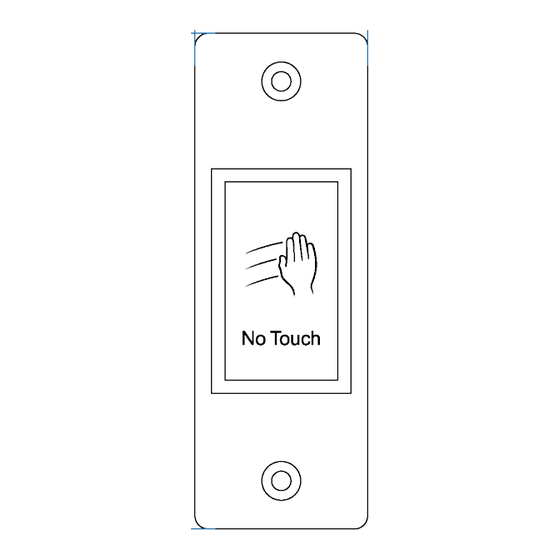
Touchless Sensor Switch, IR
Item no: 3048935 (40 x 115 x 23 mm(
Item no: 3048936 (70 x 115 x 21.5 mm)
Item no: 3048937 (86 x 86 x 20.5 mm)
1 Operating Instructions for download
Use the link
www.conrad.com/downloads
complete operating instructions (or new/current versions if available). Follow the instructions
on the web page.
2 Intended use
The product is a non-contact switch used as a trigger, making it a hygienic and convenient
solution for a wide range of applications (e.g., garage doors, building access, offices, food
preparation areas etc.).
Some features include:
■
Contactless infrared (IR) sensor switch activated with wave of hand.
■
Two colour LED sensor status lights.
■
Contact outputs: Normally open (NO), Normally Closed (NC), Common (COM).
The product is intended for indoor use only. Do not use it outdoors.
Contact with moisture must be avoided under all circumstances.
If you use the product for purposes other than those described, the product may be dam-
aged.
Improper use can result in short circuits, fires, or other hazards.
The product complies with the statutory national and European requirements.
For safety and approval purposes, you must not rebuild and/or modify the product.
Read the operating instructions carefully and store them in a safe place. Make this product
available to third parties only together with the operating instructions.
All company names and product names are trademarks of their respective owners. All rights
reserved.
3 Delivery contents
■
Non-contact panel
■
Mounting box
■
4x mounting box screws
■
4x dowels
4 Description of symbols
The symbol warns of hazards that can lead to personal injury.
The symbol warns of dangerous voltage that can lead to personal injury by elec-
tric shock.
5 Safety instructions
Read the operating instructions carefully and especially observe the safety
information. If you do not follow the safety instructions and information on
proper handling, we assume no liability for any resulting personal injury or
damage to property. Such cases will invalidate the warranty/guarantee.
5.1 General
■
The product is not a toy. Keep it out of the reach of children and pets.
■
Do not leave packaging material lying around carelessly. This may become dangerous
playing material for children.
■
If you have questions which remain unanswered by this information product, contact our
technical support service or other technical personnel.
■
Maintenance, modifications and repairs must only be completed by a technician or an
authorised repair centre.
5.2 Handling
■
Handle the product carefully. Jolts, impacts or a fall even from a low height can damage
the product.
5.3 Operating environment
■
Do not place the product under any mechanical stress.
■
Protect the appliance from extreme temperatures, strong jolts, flammable gases, steam
and solvents.
■
Protect the product from high humidity and moisture.
■
Protect the product from direct sunlight.
1
(alternatively scan the QR code) to download the
■
2x panel screws (torx head)
■
1x Torx driver
■
4x Torx screw head stickers (2x spare)
■
Operating instructions
5.4 Operation
■
Consult an expert when in doubt about the operation, safety or connection of the
product.
■
If it is no longer possible to operate the product safely, take it out of operation and pro-
tect it from any accidental use. DO NOT attempt to repair the product yourself. Safe op-
eration can no longer be guaranteed if the product:
– is visibly damaged,
– is no longer working properly,
– has been stored for extended periods in poor ambient conditions or
– has been subjected to any serious transport-related stresses.
5.5 Drilling
When penetrating the surface (example: drilling or inserting fasteners), make
sure no cables or pipes are damaged. Inadvertently penetrating electric cables
causes the life-threatening danger of an electric shock! Check for concealed
wires and pipes before drilling or inserting fasteners.
5.6 Installation or maintenance
WARNING
Risk of electric shock!
Switch the power OFF and/or disconnect the power supply at the circuit
breaker before installation or maintenance.
Always ensure that electrical work is carried out by a qualified electrician
and in accordance with local regulations and standards.
6 Installation
Important:
– Do not connect the product directly to the mains power supply.
– Use only with a 12 V/DC or 24 V/DC power source.
– Mount the product using the included electrical back box or directly to a wall using a
single-gang surface or flush-mounted electrical box.
6.1 Connection
1. Connect the wires. See section:
Wiring
2. Mount the stainless steel faceplate onto the back box using the supplied screws.
3. Apply 12 or 24 V/DC power to the product.
à
The LED indicator will light blue (standby).
4. Test for proper activation by placing a hand near the sensor.
à
The LED indicator will change to green (activated).
5. (If required) adjust the sensor read range. See section:
6.2 Wiring
Wire colour
Function
Red
Power +
Black
GND
Green
NC
Brown
COM
White
NO
6.3 Read range adjustment
■
The sensing distance can be adjusted to optimize the trigger response.
■
Remove the cover screws (1, 2) and adjust the sensor as shown.
[} 1].
Read range adjustment [} 1]
Notes
10-24 V/DC
Ground
Normally closed
Common
Normally open
Advertisement

Related Manuals for Sygonix 3048935


Summary of Contents for Sygonix 3048935
- Page 1 DO NOT attempt to repair the product yourself. Safe op- Touchless Sensor Switch, IR eration can no longer be guaranteed if the product: Item no: 3048935 (40 x 115 x 23 mm( – is visibly damaged, Item no: 3048936 (70 x 115 x 21.5 mm) –...
- Page 2 Sensor type ........active infrared, 940 nm Housing material......Stainless steel (SUS304) Operating / storage conditions..-20 to +60 °C, 10 - 80 % RH (non-condsensing) Weight (approx.) ......Item No.: 3048935: 127 g Item No.: 3048936: 130 g Item No.: 3048937: 130 g 9.2 Dimensions...
Need help?
Do you have a question about the 3048935 and is the answer not in the manual?
Questions and answers