Table of Contents
Advertisement
Quick Links
Advertisement
Table of Contents

Related Manuals for DSI JET-EA-BP

Summary of Contents for DSI JET-EA-BP
- Page 1 JET Hardware User Guide USER MANUAL Publication MU00287 Rev #10...
-
Page 2: Table Of Contents
Table of Contents Essential Safety Notes ..............................4 Environmental Conditions ............................4 Hazards and Warnings............................... 4 FCC Notice ................................. 4 Industry Canada Notice ............................. 5 EU Notice – Declaration of Conformity ........................5 Battery Information..............................5 Disclaimer .................................. 5 Product Warranty ..............................5 Product Repairs ................................. - Page 3 Basic Information ..............................27 Discussion ................................27 Conclusion and Recommendation .......................... 28 Contact Information ..............................29 Data Sciences International (DSI) ..........................29 DSI Technical Support ............................29 Page 3 JET Hardware Manual • Publication MU00287 REV 10• www.datasci.com ©2024 Data Sciences International...
-
Page 4: Essential Safety Notes
Storage Conditions: -20°C (-4°F) to 60°C (140°F); 5% - 95% Rh, Non-condensing Hazards and Warnings This instrument is subject to the following identified hazards: DSI cannot guarantee the safety of this device if used other than intended or used by any procedures other than those described in this manual. FCC Notice The JET subject’s device contains FCC ID QOQWT12 which complies with part 15 of the FCC Rules. -
Page 5: Industry Canada Notice
Repair of a damaged circuit board is not feasible. . Verification DSI hardware and software are extensively tested and calibrated before leaving our factory or warehouse. Researchers should independently verify the basic accuracy of materials delivered. Page 5 JET Hardware Manual •... -
Page 6: About This User Guide
About This User Guide This User Guide provides instructions on how to set up and operate the DSI JET System. The DSI JET™ System is designed to be used in conjunction with the Ponemah™ Physiology Platform (P3 Plus)/Life Science Suite ... - Page 7 Figure 2 JET-3ETA-BP Device The JET Receiver can accommodate up to six JET-EA-BP, four to six JET-3ETA-BP or four JET-5ETA-BP devices. The receiver needs to be placed in the animal room, but does not need to be in an animal cage. Multiple receivers can be used in the same room to record from a total of 36 JET devices per room via multiple systems.
-
Page 8: Specifications
Ponemah systems and multiple JET receivers, it is possible to monitor 36 animals in a single animal room using JET-EA-BP or JET-3ETA-BP devices or 18 per room using JET-5ETA-BP devices. Specifications JET Device Models Figure 4 JET-3ETA-BP Device There are 3 different models of JET devices. -
Page 9: Jet Receiver
Figure 6 JET Receivers Model 272-0241-001 The JET receiver transfers data from individual JET devices to the data acquisition and analysis software. The receiver can receive signals from up to six JET-EA-BP’s, four to six JET-3ETA-BP’s or four JET-5ETA-BP’s devices at one time. -
Page 10: Mechanical Specifications For Jet Device
Mechanical Specifications for JET Device Length: 2.5 Inches (6.35 cm) Width: 1.1 Inches (2.8 cm) Height: 3.7 inches (9.45 cm) Total Volume 168 CCs Weight 150 grams Note: The dimensions do not include the lead sets. The lead sets will add about 15 CCs to the total volume. -
Page 11: General Specifications For Jet Receiver
General Specifications for JET Receiver Animals Per Ponemah (P3) system Up to 16 Transmission range between device and receiver 10 meters Number of JET devices per receiver Up to 6 (dependent on device type) Receiver connection to P3 system Typically the Receiver is connected through an Ethernet switch and Router combination and that can be connected directly to computer via an Ethernet cable through a network card or into a local area... - Page 12 Figure 8 JET Receivers with dimensions Page 12 JET Hardware Manual • Publication MU00287 REV 10• www.datasci.com ©2024 Data Sciences International...
-
Page 13: Lead Sets
Lead Set The following table identifies the compatible lead set for each of the JET models. JET Model Lead sets used by the device JET-EA-BP JET-3ETA-BP B or C JET-5ETA-BP Needs 2 lead sets, can be any combination of B or C Page 13 JET Hardware Manual •... -
Page 14: Monitoring Ecg With Jet And A 3 Channel Ecg Lead Set
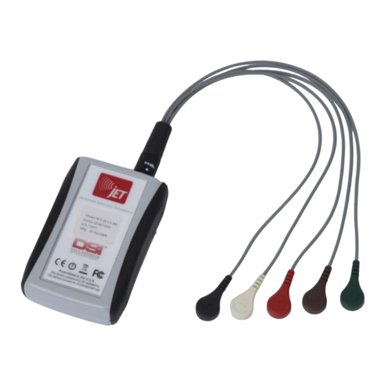
Monitoring ECG with JET and a 3 Channel ECG Lead Set The primary use of the JET system is to monitor ECG. The JET devices use standard ECG skin electrodes. The color coding for the provided 3 Channel ECG lead set is based on the Association for the Advancement of Medical (AAMI) standards. -
Page 15: To Instrument A Dog For Measurement
The minimum jacket pocket dimensions are shown in Figure 7. Jacket 1/dog Contact your DSI Salesperson for a list of companies providing jackets that have been optimized for use with JET devices. A method of compressing and holding the electrodes in place and/or... -
Page 16: To Attach The Electrodes
Pocket Location on the Jacket The recommended pocket location is either on the back or flank depending upon the animal being used. If the pocket is located on the back, it should be located close to the tail of the animal (with the top of the pocket toward the head). -
Page 17: To Install The Jet Device And Connect The Ecg Leads
Figure 11b. Alternative ECG Lead placement for dogs (without Respiration) 5. Attach the leads to the electrodes. 6. Make sure the electrodes adhere adequately to their sites. 7. Route the thermistor and electrode leads to where the jacket hole will be when the jacket is on the animal. -
Page 18: To Place The Respiratory Inductive Plethysmography (Rip) Bands
To Place the Respiratory Inductive Plethysmography (RIP) Bands 1. Select the proper size band for the test subject and strap around the abdomen (above the navel and below the ribcage) and chest (just distal to the forelimbs). Refer to Figure 9. A snug undershirt may be used if available. -
Page 19: Attaching Leads To Band Sensors
Attaching Leads to Band Sensors Figure 13 Abdomen and Chest Electronics Modules A variable gain pot screw is located on the side of each electronics module. Turning the gain counter-clockwise until a click is noticed provides the minimum gain setting. Maximum gain is achieved by turning the gain clockwise. To determine proper gain settings start with minimum gain (full counter clockwise) and increase (turn clockwise) until minimum useable signal is observed. - Page 20 Figure 14 Attachment of Modules to Bands The Chest and Abdomen modules should be connected to the 3 Channel Differential Lead as pictured in Figure 12. The Chest Module should be connected to the White snaps and the Abdomen Module should be connected to the Red snaps.
-
Page 21: Cleaning The Sensors
Cleaning the Sensors The bands are machine washable. • • Wipe the sensor and cable with a non-corrosive (to plastic) cleanser to clean before use. • Make sure the complete sensor assembly is thoroughly dry before reusing it. To sterilize the sensors / bands, use standard gas sterilization procedures. •... -
Page 22: To Clean The Jet Device And Leads
Figure 17 Back of JET device with battery removed Plug the DSI-supplied charger into a standard wall outlet, and then insert the battery into the charger bay such that the metal plates on the battery line up with the contacts in the bay. -
Page 23: Room Setup Recommendations
Room Setup Recommendations Purpose This section provides a brief summary of DSI’s recommendations on setting up an animal room for use with the JET System. It will focus on where to locate your JET Receivers, room considerations, how to connect receivers to power and the network, and how to protect receivers. -
Page 24: Required Utilities
IP address on the same subnet though some firewall or security settings may need to be modified by your IT group. DSI would also recommend that your IT group define DHCP lease times that are at least 14 days (preferably 30 days) in length. If using a corporate network with static IP addresses the JET Receivers, E2S-1, and Ponemah computers will require static IPs in the same subnet. -
Page 25: An Example Installation
typically require modification for your application. Some customers like to install these on the ceiling, others on the wall, and others on rollaway carts. An example installation In the simplest implementation, you could have waterproof boxes mounted throughout the room. Inside each box would be a mounting bracket and Ethernet port. -
Page 26: Troubleshooting
Troubleshooting Problem Cause Solution The battery needs to be Charge the battery. recharged. The battery is not connected Check the battery connections There is no signal from the JET correctly to the JET device. and correct as necessary. device. Check the ECG or RIP lead The ECG or RIP leads are not connections to the JET device connected to the JET device. -
Page 27: Appendix: Lithium Ion Battery Storage Recommendations
Appendix: Lithium Ion Battery Storage Recommendations Background DSI’s JET System was designed to use a lithium ion rechargeable battery in order to reduce the cost of use and to have less impact on the environment. This paper will provide recommendations for maximizing the operational life of your lithium ion battery. -
Page 28: Conclusion And Recommendation
Conclusion and Recommendation Lithium ion batteries have a finite life and will require replacement every 1 to 3 years depending upon use and storage conditions. To maximize the time for which the lithium ion battery has a capacity of >24 hours it is recommended to store the battery at 4-10 C (40-50°F) between uses and/or store with the battery in a partially discharged state. -
Page 29: Contact Information
We are available to help you with your questions and concerns. Should you hit a roadblock or need some additional training, please feel free to visit the DSI Support Center at https://support.datasci.com to find articles and helpful information in our knowledge base, chat with an agent, or setup time to receive one-on-one consultation. We are happy...
Need help?
Do you have a question about the JET-EA-BP and is the answer not in the manual?
Questions and answers