
Summary of Contents for Dick's Sporting Goods Ethos ETHC200
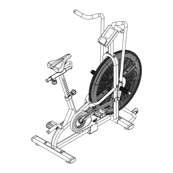
- Page 1 ETHC200 ETHOS AIR BIKE OWNER’S MANUAL DICK’S Sporting Goods 345 Court Street Coraopolis, PA 15108...
-
Page 2: Table Of Contents
TABLE OF CONTENTS SECTION PAGE BEFORE YOU BEGIN IMPORTANT SAFETY NOTICE IMPORTANT CARE AND MAINTENANCE IMPORTANT OPERATIONAL INSTRUCTIONS WARNING LABEL PLACEMENT PARTS LIST ASSEMBLY INSTRUCTIONS 7-13 EXPLODED DIAGRAM CONSOLE INSTRUCTION 15-24 BLUETOOTH APP CONNECTION INSTRUCTIONS 25-35 LIMITED WARRANTY 36-37 BEFORE YOU BEGIN Thank you for selecting the ETHOS AIR BIKE. -
Page 3: Important Safety Notice
IMPORTANT SAFETY NOTICE For your safety and benefit, read the following instructions carefully prior to assembly or use.Failure to follow all instructions and safety precautions can result in serious injury or death or damage to equipment. 1. USERS SHOULD CONSULT WITH THEIR PHYSICIAN BEFORE BEGINNING ANY EXERCISE PROGRAM. -
Page 4: Important Operational Instructions
IMPORTANT! OPERATIONAL INSTRUCTIONS This product is designed to be used for weight training, exercise, and physical fitness activities. This exercise equipment is intended for commercial and residential use. This equipment meets the safety and performance requirements of the ASTM F2276 standard for exercise equipment. - Page 5 ETHC200 PARTS LIST Part # Description Main Frame Rear Stabilizer Linkage Arm-Right Front Stabilizer Seat Slide Rail Fan Wheel Assembly Handle Bar - Right Handle Bar - Left Fan Cage - Right Fan Cage - Left Middle Hub Assembly Linkage Arm - Left Console Mast Console Pedal -Right...
- Page 6 Handle End Cap φ1 ” Ball-Bearing 6003ZZ Set Screw Handlebar Pivot Handle Bar Grip φ35×φ27×300 Button Head Screw M10 x ” Lock Washer M10 Flat Washer M10 Ball-Bearing 6000 Pop Pin Knob Bottom Bracket Retaining Ring Phillips Screw M5x ” Bell Crank - Left Handle Bar Grip φ31×φ24×110 Crank/Bell Crank Fixing Bolt...
- Page 7 Self Tapping Screw ST4.2× ” Speed Sensor Mounting Bracket Cable Bushing φ ” Speed Sensor Cable Rivnut Saddle Seat Slide Bushing Button Head Screw M8x1” Lock Washer M8 Flat Washer M8 Flat Washer φ9xφ32x2.0 Socket Head Screw M8× ” Seat Slide End Cap Drive Cog 14T Drive Cog Locking Chain Wheel 46T...
-
Page 8: Assembly Instructions
ASSEMBLY INSTRUCTIONS Tools Required for Assembly:... - Page 10 1. Align the front stabilizer (4) with the receiver on the main frame, and re-install the two screw,lock washer and flat washer assemblies (33, 34 &35) with the supplied 6mm hex wrench. 2. Repeat step 2 for the rear stabilizer (#2).
- Page 11 1. Inspect the console cable (62) for damage before threading it through the bottom side and out the top of the console mast (13). 2. Install the button head screw, lock washer and flat washer assemblies (66, 67 & 68) through the console mast base (13) and into the main frame.
- Page 12 1. Place the right handlebar assembly (7) on the floor extending forward and away from the right linkage arm (3). Remove the lock nut (58) and set aside. 2. Slide the right linkage arm (3) onto the Lower Pivot Pin and re-install the lock nut (58) with the provided 13mm wrench.
- Page 13 1.Remove the hex screw (70) and flat washer (69) from the end of the Seat Post Assembly. 2. Loosen the seat clamp assembly that is pre-installed onto the rails of the seat (64) and slip the assembly onto the knurled portion of the seat slide (5). Ensure the seat is level with the ground and fix both nuts firmly and evenly.
- Page 14 5. Loosely thread the left pedal(16) into the left crank Arm(17) by hand. NOTE: The threads are reversed; rotate the axle counter-clockwise when viewed the outboard end of the pedal to install. Use the provided wrench to firmly fix the pedal.
-
Page 15: Exploded Diagram
EXPLODED DIAGRAM... -
Page 16: Console Instruction
CONSOLE INSTRUCTION 10-20 Interval Target Time Target Distance 20-10 Interval Target Calories Custom Interval Target Heart-rate Down Start/Pause Stop Enter Display function: Item Description TIME Display user workout time Display range 0:00~1:59:00 DISTANCE Display user workout distance ... - Page 17 Button function: Item Description Adjust function value up. Adjust function value down. Down Enter Confirm setting or selection. Start Start workout quickly or resume workout in Stop mode. To stop/pause workout. Stop Hold on this key for 2 seconds to reboot the console. Three program options: Interval 10/20, Interval 20/10, or Custom ...
- Page 18 Figure3 1.Break mode: To start Break Mode, press the "START" button one time. Entering Break mode will create a 0.5 second buzzer sound every 30 seconds. The computer will still display all functions, but the LCD windows will display "P". Buzzer will sound for 1 second and enter into standby mode after a break has lasted 5 minutes.
- Page 19 (Figure 5) 3.Quick start : In standby mode with pedalling greater than 20 RPMs, press "START". The buzzer will sound for 0.5 seconds and then TIME, CALORIES, DISTANCE, WATTS, SPEED, and RPM will display in sequence. The value will count up according to the operation. The "PULSE"...
- Page 20 and the TIME icon counts down from 10 seconds to 0. The LCD will display DISTANCE, CALORIES, WATTS, SPEED, and RPM (Figure 8). (Figure 7) (Figure 8) After exercising for 10 seconds, the LCD will display "01/08" with "01" flashing. The "REST"...
- Page 21 (Figure 10) After exercising for 20 seconds, the LCD will display "01/08" with "01" flashing. The "REST" icon will flash and a buzzer will sound every second as TIME counts down from 10 seconds to 0. WORK and REST will display in sequence and the cycle count will increase by 1 after each REST/WORK cycle until "08/08"...
- Page 22 (Figure 14) (Figure 15) (Figure 16) 7.TARGET TIME: Press "TARGET TIME" to enter this mode. The LCD will display "TARGET" & "TIME". The TIME window will display 1:00. Press "UP" or "DOWN" to adjust from 1:00 to 1:59:00. Press "ENTER" to set the desired time and begin exercise. The target time will count down to 0.
- Page 23 9.TARGET DISTANCE: Press "TARGET DISTANCE" to enter this mode. The LCD will display "TARGET" & "DISTANCE". The DISTANCE window will display 0.5. Press "UP" or "DOWN" to adjust from 0.5 to 100.0 .Press "ENTER" to set the desired distance target and begin exercise. The target distance will count down to 0.
- Page 24 the user to accelerate. If the pulse is more than 10% above the target value, the "DOWN" icon will display reminding the user to slow down. If the heartbeat value is higher than 100%, the buzzer will ring three times per second for up to 10 seconds. If the heart rate value does not go below 100%, the buzzer will ring for 1 second and then enter standby mode.
- Page 25 Battery installation instruction : A. Remove the battery cover on the back of the console. B. Replace 1.5V (AA) battery. C. Make sure the battery is installed correctly and the polarities are correct. Note: 1. required only for devices which use more than one battery in one circuit, Do not mix old and new batteries;Do not mix alkaline, standard (carbon-zinc), or rechargeable (Ni-Cd, Ni-MH,etc.) batteries.
-
Page 26: Bluetooth App Connection Instructions
Bluetooth APP connection instructions Connection steps of Iconsole +, Kinomap & Zwift APP(FTMS) 1. iConsole+ APP Connection steps Open iConsole+ APP enter into the home page, choose Quick Start or other training mode. Select the Bluetooth device, then press the arrow key in the upper right corner to enter the training screen. - Page 27 Press the screen will display pause button ( Stop training) and stop button ( End training ) . 2. Kinomap APP connection steps Open the Kinomap + App and enter the home page. Click the button in the lower right corner“More”to add new devices.
- Page 28 Click “equipment management”, then click the "+" symbol in the upper right corner to start adding equipment. Click “Bike” graphics, then enter a variety of brand connection screen, select ICONSOLE or FTMS. Once the user selected ICONSOLE, click on "iBiking 10 levels" under SMART and then select the Bluetooth device.
- Page 29 Once the user selected FTMS , click on "Exercise Bike" under INTERACTIVE, and then select the Bluetooth device. Fill in the brand and model of the Bike.
- Page 30 Click to add a new device.(IOS does not have this screen setting, Android needs to select to add a new device.) Press the Home button to return to the Home page after adding the device. ...
- Page 31 To select the training video, you must select the type of Bike and press the button to enter the training screen. Start pedaling. Pressing the pause button at the top of the screen to stop. ...
- Page 32 Enter the pause screen and you can choose to continue or exit to end the training. ...
- Page 33 3. Zwift APP connection steps Open the Zwift app and select the user. Enter the device connection screen. Click the Bluetooth device to connect the three devices below, and press the start button to enter.
- Page 34 Click on exercises Video&Mode, then press START RIDE.
- Page 35 Enter the training screen to start pedaling, you can manually adjust the resistance of the console . Press any part of the screen will appear the option, click the option button in the lower left corner to enter the pause. 、...
- Page 36 You can choose to continue or end the training. ...
- Page 37 DICK’S LIMITED WARRANTY DICK’S warrants the products described above to be free from defects in workmanship and materials as follows: Who is Covered? This limited warranty (“Limited Warranty”) covers only the person who first purchased the product. This Limited Warranty expires at the time of transfer and is not transferable to anyone else.
-
Page 38: Limited Warranty
What DICK’S Will Do to Correct the Problem Once you make a valid warranty claim, DICK’s will either: Return or exchange the product; or Provide a free replacement part, if applicable; or Repair the product for free, if applicable. ...
Need help?
Do you have a question about the Ethos ETHC200 and is the answer not in the manual?
Questions and answers