Table of Contents
Advertisement
Quick Links
Advertisement
Table of Contents

Summary of Contents for MediTek MT-ECT10
- Page 1 MT-ECT10 EMERGENCY CLINICAL TOUCH SCREEN ALARM PANEL INSTALLATION & OPERATING MANUAL (Ver 3.2) 8 Park Edge Mews 21 Link Way, Edgemead, 7407 Cape Town RSA Tel (27) (021) 558-7040 gas@mediteksystems.co.za www.mediteksystems.co.za SAHPRA No 00002150MD...
-
Page 2: Table Of Contents
INDEX PAGE DESCRIPTION WIRING SCHEMATIC SETUP WIZARD MENU SETTINGS 4 - 7 • Layout • Configuration • Location • Date/Time • Installer • Alert Contact DIAGNOSTICS EVENT HISTORY MAINTENANCE SPECIFICATIONS 10. DIMENSIONS 11. TROUBLESHOOTING 12. WARRANTY... -
Page 3: Description
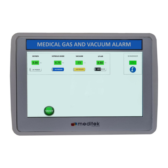
DESCRIPTION Housed in an ABS Bopad enclosure, this Digital Emergency Clinical Alarm panel monitors up to 8 critical gas line pressures. An additional input is also provided to monitor a Voltage Free (VF) switch such as a scavenger. The full colour 10.1” touchscreen displays individual pipeline gases and their current pressures. - Page 4 SCHEMATIC WIRING DIAGRAM Sensor Control & PSU Page 2...
-
Page 5: Setup Wizard
SETUP WIZARD On initial power-up, the system will enter the Setup Wizard which will take you through a step by step process of configuring your alarm panel. Press Next Press Next Page 3... - Page 6 SETUP WIZARD Continued… Press Next Press Next Page 4...
- Page 7 SETUP WIZARD Continued… Press Next Press OK This concludes the Setup Wizard. All of these settings are available for amendment from the setting icon on the menu page. Page 5...
-
Page 8: Menu
MENU Each alarm system is programmed and calibrated before leaving the factory and no maintenance or adjustment should be required. If any of the alarm details or alarm levels needs to be changed, this may be done by qualified personnel only. Touch on the settings icon to access the system management menu. -
Page 9: Settings
SETTINGS All alarm settings relevant to the system will be displayed and changes can be made in real-time. The screen will automatically return to the home “Monitor” screen after 10 seconds of inactivity. Use Back icon to return to previous page. Touch on the layout icon to select alarm inputs display layout. - Page 10 SETTINGS Continued… Touch on the configuration icon to amend the alarm inputs settings. All alarm inputs are displayed with relevant position on the display screen. Touch on required alarm input to amend. Adjust required alarm information and swipe left/right for next alarm input or back arrow. Page 8...
- Page 11 SETTINGS Continued… Touch on the location icon to amend the alarm system location/area. Select appropriate hospital group/name and location. Touch on the date/time icon to amend the system date & time. Page 9...
- Page 12 SETTINGS Continued… Touch on the installer icon to amend the installer’s company information. Select the appropriate installer and provide contact number. Touch on the alert contact icon to amend the alert notification information. Provide the alert notification responsible person and contact details. Page 10...
-
Page 13: Diagnostics
DIAGNOSTICS Touch on the diagnostics icon to view the current incoming sensor data. This data represents the raw sensor information being received by each input. MANUAL Touch on the manual icon to see a full description of: • Description/features • Specifications •... -
Page 14: Event History
EVENT HISTORY By pressing on the required gas symbol, the relevant date stamped history will be displayed, showing the latest 50 events. Page 12... -
Page 15: Maintenance
MAINTENANCE This alarm system has no user-serviceable parts. Monthly check • Throttle each line pressure and check that an alarm condition is registered. • Press MUTE button to confirm the alarm sound is muted. • Press TEST button to confirm all displays and alarm buzzer are working. Annual check •... -
Page 16: Specifications
SPECIFICATIONS POWER SUPPLY • 80 to 240 Volt ac 50 Hz supply 36W. • Resettable surge suppressers. • 12V standby charger with Li battery (optional). • 12VDC 3A output • Fuse 22mm 3A glass cartridge. INPUTS • 7 x 4-20mA pressure sensor •... -
Page 17: Dimensions
DIMENSIONS Page 15... -
Page 18: Troubleshooting
TROUBLESHOOTING The MT-ECT10 Alarm System contains no user serviceable components. All repairs and maintenance must be carried out by qualified, Meditek Systems’ appointed personnel. Failure to comply may render any warranty null and void. Changing any settings may cause the entire alarm network to malfunction and void the warranty. -
Page 19: Warranty
• Improper maintenance or failure to perform regular preventative maintenance Meditek Systems does not accept liability beyond the remedies provided for in this limited warranty or for any special, indirect, consequential or incidental damages, including without limitation, any liability for third party claims against you for damages. Meditek Systems ’s maximum liability will be no more that the amount you paid for the product that is subject of the claim.
Need help?
Do you have a question about the MT-ECT10 and is the answer not in the manual?
Questions and answers