Table of Contents
Advertisement
Quick Links
Advertisement
Table of Contents

Related Manuals for Space-Ray Zephyr


Summary of Contents for Space-Ray Zephyr
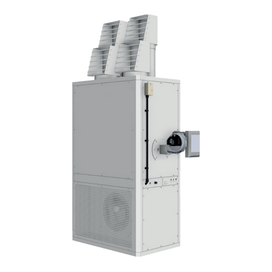
- Page 1 ® INSTALLATION MANUAL Model Zephyr...
-
Page 2: Table Of Contents
Contents Page Page General Storage tank Introduction Single pipe (gravity feed) General health and safety Two pipe system 1.2.1 Gas leak emergency Pressurised ring main system 1.2.2 Before using this appliance Pipework and fittings Indirect fired Condensate Drains Factory test 10. -
Page 3: General
• Do not store or use petrol or other flammable vapours and liquids in the vicinity of the appliance. Zephyr is the latest generation of heat module, combining • In case of persisting problems, contact your innovative design with proven heat exchanger technolo-... -
Page 4: Before Using This Appliance
Carefully read these instructions and follow the 1.5 Construction processes explained by the manufacturer. These in- The construction of a Zephyr will consist of double skin structions are only valid for appliances designed to panels all around. External units will be fully water proof;... -
Page 5: Technical
2. Technical 2.1 Technical Data TECHNICAL DATA - Zephyr Series Models Nominal Heat Output Heat Input °C Temperature Rise Thermal Efficiency (Nett CV) Min 92% mg/kW Nox Emission 58.2 62.3 65.3 62.1 65.9 61.0 63.5 65.3 66.2 61.0 65.2 60.2... -
Page 6: General Requirements
• The position of the heater relative to the supply of cations and codes. Space-Ray recommends the in- fresh combustion air. staller contact a local Building Inspector, Fire Officer or Insurance Company for guidance. -
Page 7: Heater Installation
• To use the information given in the manual togeth- Wall er with the local and national codes to perform the installation. Flue Flue 1000 1000 • To install the heater in accordance with the Clear- ances to Combustibles of this heater. Internal model External model •... -
Page 8: Supply Air Ductwork
3.4.3 Airflow fitting of any spares, which may be required. The Zephyr It is essential that the correct amount of air is provid- is designed to be installed nozzle head or in ductwork. -
Page 9: Overheat Protection Device
and insulation are prime considerations. Joints and seams To reset the Jumo overheat the right hand side stat shown must be airtight and fastened securely and designed to in Fig 2, remove the plastic cap (A) with a screw driver and remain so, even when operating at high temperatures. -
Page 10: Flue Arrangement
Reliance on doors and win- dows is not permitted. 5.2 Flue arrangement The Zephyr heaters are designed as a Type B23 forced Always ensure that an adequate inlet for fresh air for com- draught heater were the combustion air is taken from the... -
Page 11: Flue Terminal
It is important to ensure that there is an adequate air sup- It is important for the terminal of an individual open flue ply at all times for both combustion and heating require- system to be located so that it is not likely to be subjected ments. -
Page 12: Gas Supply
4. Unless the heater is suspended or movement is ap- Note The fuel supplier should be contacted prior to Note: parent, the Zephyr must be connected with medi- installation so that any requirements concerning delivery, um, heavy or copper pipe; otherwise the use of an... -
Page 13: Single Pipe (Gravity Feed)
pipe with a diameter greater than that of the filler feed pipe should extend to not less than 100mm above and featuring a weatherproof termination. the bottom of the tank. A none return valve with a metal • A sludge valve. to metal seat should be fitted, especially if the return •... -
Page 14: Condensate Drains
This solution, however, is less safe than the Zephyr heaters are supplied for use on 415V 50Hz 3PH previous one, due to the possibility of leakage in the & 240v 50Hz 1PH supplies as standard. Single phase is valve. -
Page 15: Ventilation
• If confused, please contact manufacturer for fur- terminals 9 (0V) & terminal 11 (10V DC) - The fan will not ther clarification. operate unless one of the two options above has been • Install upstream of the unit a differential magneto used. - Page 16 are factory set. For further information please see 7. Make sure that all dampers are set and diffuser out- the burner manual. lets are open to give the correct air flow. 15. Burnertech Modulating Burner - once high fire is 8.
-
Page 17: Servicing
• Heater running temperature and overheat set- Burner Removal (With gas and electrical supply isolated): tings. • Full thermal input. 1. Disconnect the electrical supply to the burner by • Governor pressure setting (pilot for start gas and removing the multi-pin plug from the socket on main for full fire). -
Page 18: Recommended Intervals
is important to inspect the gasket material and replace if for 10 to 15 minutes to dissipate residual heat. necessary. 14.7 Fan control (if used) It is important that the tubes should be inspected and The burner should start it’s safety sequence and then fire swept out if necessary, replacing Gasket Material –... -
Page 19: Removal And Replacement Parts
joint must be repaired. Fault Cause Check Summer/winter switch 15. Removal and Replacement Parts set to summer (manual) Main fan runs NOTE: Note! Please refer also to the burner supplement sup- Electrical Fan thermostat set to continuously plied with this Manual. Faulty fan/limit stat 15.1 Multi-Block gas valve Fan motor faulty... - Page 20 Simple Fault Finding • Some possible reasons for the heater not operat- ing are: • Gas supply not turned ON. • Electrical Supply not turned ON. • The time and/or Thermostats may not be ON. • The Limit stat may have operated due to an interruption of electrical supply or fault with the distribution fan.
-
Page 21: Wiring Diagrams
18. Wiring diagram Wiring diagram for gas models fitted with Burnertech burner... - Page 22 Wiring diagram for oil models...
- Page 23 Notes...
- Page 24 ® Gas Fired Products (UK) Ltd Chapel Lane Claydon, Ipswich Suffolk, IP6 0JL Tel: +44(0)1473 830 551 www.spaceray.co.uk info@spaceray.co.uk FACTORIES: IPSWICH, ENGLAND - CHARLOTTE, N.C, U.S.A Zephyr Manual February 2024...
Need help?
Do you have a question about the Zephyr and is the answer not in the manual?
Questions and answers