Table of Contents
Advertisement
Quick Links
Advertisement
Table of Contents

Related Manuals for SNR ROME RE Series

Summary of Contents for SNR ROME RE Series
- Page 1 ROME platform 2U two-way server quasi-system User operation manual V1.0...
- Page 2 This ROME dual-channel high-density server of SNR is divided into various models, such as 2U8, 2U12, 2U25, 4U24 and 4U36. This product has low energy consumption and flexible expansion This manual is mainly for 2U models (model: SNR- SR2208RE;...
- Page 3 Chapter II Product Introduction This section provides the specifications of the main components of the system and describes the main characteristics of each model of SNR RE series. Chapter III Installation of System Components This section describes the installation methods and main precautions of various main system components using Rome dual cabinet server.
- Page 4 Explanation: noun interpretation AMD EPYC™ ROME series processors 7002 The white gold certified power supply is the "80 PLUS Platinum" standard, that is, the conversion White gold medal efficiency power rate of 20% load is supply Over 90%, the conversion rate of 50% load is over 94%, and the conversion rate of 100% load is over 91% M.2 interface is a new generation interface standard tailored for Ultrabook, which is Intel ®...
- Page 5 Peripheral Component Interconnect PCIE Extended bus standard for high-speed serial computers Express Universal Serial Bus Universal serial bus Firmware firmware Trusted Platform Module Trusted platform module Input/Output in-out BIOS Basic Input-Output System Basic Input/Output System CMOS Complementary Metal Oxide complementary metal oxide semiconductor Semiconductor Management Engine Management engine...
- Page 6 Symbolic convention: Note: If it is used to transmit equipment or environmental safety warning messages, it may lead to equipment replacement, data loss, equipment performance degradation or other unpredictable results. Warning: used to warn of potential dangerous situations, which may lead to death or serious personal injury.
-
Page 7: Table Of Contents
Catalogue The first chapter safety statement ............................. 11 1.1 General safety matters .............................. 11 1.2 Name and content identification table of toxic and harmful substances or elements in products ....... 12 1.3 Warning notice ................................. 13 1.4 Climatic and environmental requirements ......................... 13 1.5 Other important descriptions ............................ - Page 8 5.2.2 Main menu description ..........................63 5.2.3 Advanced menu description ........................64 5.2.4 Trusted Computing............................ 66 5.2.5 PSP Firmware Versions ..........................67 5.2.6 Boot Feature ............................. 68 5.2.7 NB Configuration ............................69 5.2.8 Memory Configuration ..........................71 5.2.9 Socket 0/1 Information..........................72 5.2.10 PCIE Port Bifurcation ..........................
- Page 9 7.1.2 Enter BIOS to set IPMI function ........................182 7.1.3 IPMI interface configuration Static mode ......................185 7.1.4 IPMI configuration Java SOL ..........................186 7.2 Introduction of IPMI function ...........................187 7.2.1 Enter the operation interface .........................187 7.2.2 Default user name and password ........................189 7.2.3 IPMI management system content ........................189 7.2.4 Introduction to KVM remote management ......................191 7.2.5 Introduction to KVM page ..........................192...
-
Page 10: General Safety Matters
Chapter one Safety statement General safety matters To prevent the risk of significant personal and property damage, please follow the following suggestions. Please do not open the cover plate of the system by yourself. It should be operated by professional trained maintenance technicians. -
Page 11: Name And Content Identification Table Of Toxic And Harmful Substances Or Elements In Products
However, it complies with the EU ROHS Directive (including its exemption provisions). Note: this table shows the status of toxic and harmful substances in all possible components of SNR server, memory and workstation products. Customers can refer to this table for the toxic and harmful substances in each part of the purchased... -
Page 12: Warning Notice
Warning notice This product meets the EMC class a standard. Climatic and environmental requirements • The best working temperature of the equipment is 10 ℃ - 40 ℃; the maximum indoor environment temperature of the equipment is 45 ℃. • System battery: 3 V CR2032 lithium battery. -
Page 13: System Introduction
2.1 System introduction SNR RE series dual channel server quasi system is a dual channel cabinet server which is widely used by SNR for Internet, IDC (Internet Data Center), cloud computing, enterprise market and telecom business application. It is suitable for it core business, cloud computing virtualization, high performance computing, distributed storage, big data processing, enterprise or telecom business applications and other complex workload. - Page 14 Slots The system supports 550W, 800W, 1200W, 1300W, 1600W hot swap Power Supply redundant white Gold efficiency power supply System fan The system supports 4 8038 temperature control fans (8056 temperature control fans are optional) System size 798mm * 433.4mm * 87.6mm (L * w * h) 2u8 net weight 17.8kg, gross weight 24.55kg System weight The net weight and gross weight of 2u12 are 17.4kg and 28.55kg...
- Page 15 output voltage +12Vdc System fan Number of fans The system supports 4 8038 temperature control fans (8056 temperature control fans are optional) Fan voltage 12(10.8-12.6) Vdc Fan current 4A (4.4A Max) Fan speed 14000 + / - 10% RPM maximum Fan airflow 3.2m 3 / min (141.9 CFM), minimum 2.63m m3 / min (125.8 CFM) Fan pressure...
-
Page 16: System Architecture
2.2.2 system architecture SNR RE series server is a server quasi system based on AMD Rome platform. The system supports 2U height and the maximum support is 280W CPU, supporting up to 32 memories. The system uses a general motherboard, the motherboard name is g1dlro-b, and the front panel can support 8 / 12 / 25 SATA / SAS hard disks, of which 8 disks are referred to as 2u8, 12 disks are referred to as 2u12, and 25 disks are referred to as 2u25. -
Page 17: Introduction Of System Model Specifications
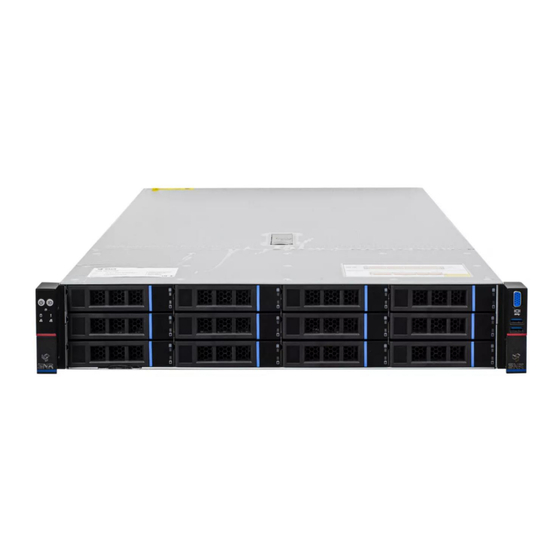
Introduction of system model specifications SNR-SR2208RE Figure 2-2 SNR-SR2208RE Product name Supports two AMD epyc 7002 series processors processor Up to 280W Motherboa G1DLRO-B rd model Support DDR4 rdimm / lrdimm / 3ds lrdimm / nvdimm-n server memory; Memory frequency supports 2666 / 2933 / 3200mhz;... - Page 18 Administrat The onboard IBMC management module supports IPMI, sol, KVM over IP, virtual media and other management features System fan Support up to 4 8038 fans (optional 8056 fans) Platinum grade 550W, 800W, 1200W, 1300W, 1600W hot swap redundant power Power Supply supply...
- Page 19 SNR-SR2212RE Figure 2-3 SNR-SR2212RE Product name processor It supports two AMD epyc 7002 series processors with a maximum support of 280W Motherboard G1DLRO-B model Support DDR4 rdimm / lrdimm / 3ds lrdimm / nvdimm-n server memory; Memory frequency supports 2666 / 2933 / 3200mhz;...
- Page 20 DB-9 COM ports Administration The onboard IBMC management module supports IPMI, sol, KVM over IP, virtual media and other management features nature System fan Support up to 4 8038 fans (optional 8056 fans) Power Supply Platinum grade 550W, 800W, 1200W, 1300W, 1600W hot swap redundant power supply (according to Actual power adaptation) Dimensions...
- Page 21 SNR-SR2225RE Figure 2-4 SNR-SR2225RE Product name processor It supports two AMD epyc 7002 series processors with a maximum support of 280W Motherboard G1DLRO-B model Support DDR4 rdimm / lrdimm / 3ds lrdimm / nvdimm-n server memory; Memory frequency supports 2666 / 2933 / 3200mhz;...
- Page 22 System fan Support up to 4 8038 fans (optional 8056 fans) Platinum grade 550W, 800W, 1200W, 1300W, 1600W hot swap redundant power supply (according to Supp Actual power adaptation) Dimensions 2U cabinet type, 798 * 433.4 * 87.6mm Table 1-7...
-
Page 23: Introduction Of System Components
Introduction of system components 2.4.1 Front panel assembly SNR-SR2208RE Figure 2-5 Serial name Serial name numb numb Built in DVD drive USB3.0 interface VGA interface 3.5 inch hard disk Table 1 - 8 SNR-SR2212RE Figure 2-6 Serial name Serial name... - Page 24 SNR-SR2225RE Figure 2-7 Serial name Serial name numb numb 3.5-inch hard disk USB3.0 interface VGA interface Front panel interface description Table 1-10 name type explai VGA interface DB15 Used to connect a display terminal, such as a display or KVM.
- Page 25 Serial Indicator light / button Serial Indicator light / button numb numb Power switch button / indicator System alarm indicator Uid button / indicator Network port 1 connection status indicator Reset restart server button Network port 2 connection status indicator Hard disk indicator Table 1-12 LED status...
- Page 26 The Ethernet port indicator of the corresponding Network port connection status network card. Green (always on): indicates that the indicator network port is connected normally. Off: indicates that the network port is not in use or fails. Note: it corresponds to two 1ge network ports on the motherboard.
-
Page 27: Back Panel Assembly
2.4.2 Back panel assembly Figure 2-9 explain: Serial name Serial name numb numb Riser module USB 3.0 interface Hard disk module Ocp3.0 interface Management Power module 1 network port VGA interface AC interface of power module 1 RJ45 gigabit Power module 2 network port COM port... - Page 28 Both 1 and 2 can be equipped with rear hard disk module or rice module. This drawing is for reference only, and the actual configuration shall prevail. Description of rear panel interface name type number explai VGA interface DB15 Used to connect a display terminal, such as a display or KVM.
- Page 29 Table 1 - 16 Indicator light / Status button descriptio Green (always on): indicates that the input and output are normal. Red (always on): indicates that the input is normal, and there is no output due to power over temperature protection, power output over-current / short circuit, output over-voltage, short-circuit protection, device failure (excluding all device failures).
-
Page 30: Motherboard Assembly
2.4.3 Motherboard assembly All models share the motherboard components, and the interface description is shown in Figure 2-11 Figure 2- Figure 2-11 number Module name 4Pin interface for 4U chassis fan control Memory slot (corresponding to cpu0) Memory slot (corresponding to CPU1) CPU0 CPU1 GPU power 2 * 4 pin interface... - Page 31 PCIE4.0 X8 PCIE4.0 X16 I350 PCIE4.0 X16 IPMI RJ45 1Gb LAN RJ45 1Gb*2 DB-9 COM port USB3.0 OCP 82599 CPU1 PCIE4.0 X16 CPU1 PCIE4.0 X8 BP HDD LED Slimline PCIE4.0 X8 CPRS PSU GPU Power CPRS PSU RISER POW BP Power FP BIN LED PMBUS/BP5 I2C FP VGA...
-
Page 32: Hard Disk Backplane Assembly
2.4.4 Hard disk backplane assembly SNR-SR2208RE expansion backplane is shown in the figure Top surface Figure 2-12 Serial desc funct number ribe The maximum support is 12g / b SAS hard SAS0~7 SAS / SATA hard disk connector disk; Support 6G / b SATA hard disk at most;... - Page 33 SNR-SR2212RE expansion backplane is shown in the figure Top surface Figure 2-14 Seria desc funct ribe The maximum support is 12g / b SAS hard disk; SAS / SATA hard disk Support 6G / b SATA hard disk at most;...
- Page 34 SNR-SR2225RE expansion backplane is shown in the figure Top surface Figure 2-16 Seria desc funct ribe The maximum support is 12g / b SAS hard disk; SAS / SATA hard disk Support 6G / b SATA hard disk at most;...
- Page 35 The SAS / SATA backplane is shown in the figure Top surface Figure 2-18 Serial descri functi numb The maximum support is 12g / b SAS hard disk; SAS / SATA connector Support 6G / b SATA hard disk at most; Support SAS / SATA hard disk hot swap.
- Page 36 U. 2 the back plate is shown in the figure Top surface Figure 2-20 Serial descri function numb Sff-8639 connector U.2 interface supporting pciex4 for connecting nvme SSD Table 1-27 Bottom surface Figure 2-21 Serial descri functi numb Provide PCIe × 4 interface to connect CPU and nvme ssd1 Slimline 4I connector 1、4 (package...
- Page 37 Riser 1 / 2 backplane is shown in the figure Figure 2-22 Serial descri functi numb 1、2 PCIe 4.0 X8 slot For connecting pcie4.0 X8 devices PCIe 4.0 x16 slot For connecting pcie4.0 x16 devices Power supply port Riser card power transmission connector for 12V power transmission PCI x16 specification gold finger Used to connect the PCIe x16 interface...
-
Page 38: Dimm Slot Location
Riser 4 backplane is shown in the figure Figure 2-24 Seria desc funct ribe PCIe x16 slot Used to connect the PCIe 4.0 x16 device PCIe X8 slot Used to connect the PCIe 4.0 X8 device Power interface Riser card power transmission connector for 12V power transmission 4、5 Slimline interface... -
Page 39: Hard Disk Label
2.4.6 Hard disk label SNR-SR2208RE Figure 2-26 SNR-SR2212RE Figure 2-27 SNR-SR2225RE Figure 2-28 2.4.7 Hard disk indicator 8-bay / 12 Bay hard disk indicator: Fault LED StatusLED Act LED Figure 2-29 function Activity indicator Positioning indicator Error indicator (yellow) (green) - Page 40 25 Bay hard disk indicator: Hard disk Activity indicator Error indicator status (green) (yellow) Hard disk not in place Hard disk in place, but no data activity The hard disk is in place and Flash rate of hard disk active itself hard disk failure Hard disk is located...
-
Page 41: Pcie Slot Distribution Rear View
2.4.8 PCIe slot distribution rear view Figure 2-30 IO module 1 provides slot slot slot 0-2, IO module 2 provides slot slot slot 3-5, IO module 3 provides slot slot slot 6- 7, and IO module 4 provides slot slot slot 8-9. IO module 1 can be equipped with two 3.5-inch hard disk modules / full height expansion modules.(1 out of 2) When selecting a 3.5-inch hard disk module (the module supports up to two 3.5-inch SAS / SATA hard disks), slot0-2 can not access any devices. -
Page 42: System Fan
2.4.9 System fan The server supports variable fan speeds. Generally, the fan rotates at the lowest speed. If the server temperature rises, the fan will increase the speed to cool down. Figure 2-31... -
Page 43: Removing And Installing Cpu
Chapter three Installing system components Removing and installing the CPU Before you begin installing the CPU, read the following guidelines: ⚫ Make sure the motherboard supports the CPU. ⚫ Before installing the CPU, be sure to turn off the computer and unplug the power cord from the power outlet to prevent damage to the hardware. - Page 44 Figure 3-2 Figure 3-3...
-
Page 45: Removing And Installing Radiator
Removing and installing radiator Before you begin installing the heat sink, read the following guidelines: • Before installing the heat sink, be sure to turn off the computer and unplug the power cord from the power outlet to prevent damage to the hardware. •... -
Page 46: Installation Of Memory
Installation of memory 3.3.1 Memory support specifications The motherboard supports DDR4 Rdimm / lrdimm / 3ds lrdimm / nvdimm-n server memory, memory frequency support 1866 / 2133 / 2400 / 2666 / 3200mhz; support single capacity of 16GB, 32GB, 64GB, 128GB, 256gb, the maximum support of the whole machine 8tb memory capacity.. -
Page 47: How To Install Memory
In addition, it should be noted that: ◆ In the same channel, the memory with large capacity must be inserted into the first one (such as A1 / B1 / C1 / D1 / E1 / F1 / G1 / H1): blue; it is not allowed to mix rdimm and lrdimm. Note: when installing two CPUs, in order to achieve optimal performance, it is recommended to install dual memory and keep the same amount of memory per CPU. - Page 48 Remove: gently push the release tabs near both ends of the memory module socket with your thumb. This should free memory from the socket. The demonstration of removing memory module is shown in Figure 3-8 Figure 3-8...
-
Page 49: Installation Of Hard Disk
3.4 Installation of hard disk • Installation of 3.5-inch hard disk: Place the hard disk in the tray There are 4 countersunk screws on the left and right sides to lock the hard disk (the screw head must not protrude from the slide surface on both sides of the tray) Figure 3-9 Figure 3-10... - Page 50 • Installation of 2.5-inch hard disk Place the hard disk in the tray Four countersunk screws at the bottom lock the hard disk (the screw head protrudes from the bottom of the tray) Figure 3-11 Figure 3-12 The hard disk tray assembly is installed in the chassis With the hard disk wrench on, push it into the chassis When the gold finger of the hard disk touches the backplane device, turn the wrench in the direction of the arrow Schematic diagram of hard disk installation in place...
-
Page 51: Installation Of Front Hard Disk Backplane
3.5 Installation of front hard disk backplane • Front hard disk backplane installation: First, take out the hard disk frame, align the screw hole on the top of the hard disk backplane with the screw hole of the hard disk frame, and then install and fix the hard disk frame and hard disk backplane with screws. Put the hard disk frame installed with the hard disk backplane down to the corresponding position of the chassis, move the hard disk frame appropriately, make the screw holes at the bottom of the frame align with the protruding screw holes of the chassis, and then install the screws to fix them. -
Page 52: Ssd Installation
3.6 M. 2 SSD installation Step 1: install the positioning stud according to the length of m.2 card to be installed. Figure 3-17 Step 2: install the m.2 card Insert the m.2 card connector into the motherboard connector as shown in the figure. Press the other end of the m.2 card to the alignment stud plane in step 1. -
Page 53: Pci-E Expansion Card Installation
3.7 PCI-E expansion card installation Step: install the PCIe card Install the PCIe card in the direction shown in the figure Rotate the PCIe card latch According to the arrow scheme, lock the lock of the PCIe card Figure 3-20 Figure 3-21 Figure 3-22... -
Page 54: Pci-E Module Installation
3.8 PCI-E module installation Installation steps of riser1-3 module: place the rear window PCIe component vertically and downward - align the PCIe slot, align the positioning hole, and place it flush with the rear window. Figure 3-23 Installation steps of riser4 module: place the rear window PCIe component vertically and downward - align the PCIe slot with the positioning hole, place it flush with the rear window, and then lock the side screw Figure 3-24 Step 1: rear hard disk module backplane installation... -
Page 55: Installation Of Rear Hard Disk Module
Figure 3-25 Figure 3-2 3.10 installation of rear hard disk module • Installation of rear 3.5 inch hard disk module Step 1. Place HDD tray vertically down and flush with the rear window step 2. Fix the rear HDD tray assembly... - Page 56 Step 3. Lock a loose screw Figure 3-27 Figure 3-28...
- Page 57 ⚫ Installation of rear 2.5 inch hard disk module Place vertically downward and align with the guide pin at the lower end After leveling, push it to the end in the direction of the arrow, Lock the screw Figure 3-29 Figure 3-30...
-
Page 58: Installation Of Power Supply Module
3.11 Installation of power supply module Step: push the power supply to the bottom in the direction of the arrow, and the spring wrench on the right side makes a click sound, indicating that it is installed in place; Figure 3-31 Figure 3-32... -
Page 59: Installation Of Fan Module
3.12 Installation of fan module Step: place the fan module vertically downward in the direction of the arrow (note that the fan module faces) Figure 3-33 Figure 3-34... -
Page 60: Installation Of Wind Deflector
3.13 Installation of wind deflector Steps: align the wind guide module with the hanging points on the left and right sides, and place it vertically downward - the height is lower than the box height Figure 3-35... -
Page 61: Installation Of Optical Drive
3.14 Installation of optical drive Step: install the optical drive Install the fixing part of the optical drive in the direction of the arrow, and lock the pan head screw Figure 3-36 Align the opening of the optical drive position on the chassis, and push the optical drive in the direction of the arrow until the fixed parts are locked automatically. -
Page 62: Installation Of Upper Cover Of Chassis
3.15 Installation of upper cover of chassis Step 1: install the rear upper cover of the chassis The hanging nail of the upper cover shall be aligned with the opening position of the box body and placed downward Rotate the upper cover latch in the direction of the arrow to lock it in place Figure 3-39 Figure 3-40... - Page 63 Chapter four System cabinet installation 4.1 Installation of inner rail of guide rail Step 1. Prepare two sliding rail and pull out the inner rail. Step 2. Fix the inner rail on both sides of the chassis. Figure 4-1 Figure 4-2...
-
Page 64: Install The Outer Rail To Cabinet
4.2 Install the outer rail to cabinet Step 3. Install the outer rail on the cabinet bracket and tighten the screws. Note: when installing the guide rail, align with the U-Mark, and install it in place with a snap, and use M5 screw to firm it. Figure 4-3... -
Page 65: Install The Server To Cabinet
4.3 Install the server to cabinet Step 4. Align the chassis with the inner rail to the outer rail for installation. Note: when you can push the chassis forward, you can hear a crack. If you can't push it, you need to pull down the inner rail buckle to continue to push the chassis gently. -
Page 66: Enter The Bios Setup Interface
Chapter five BIOS parameter setting description 5.1 Enter the BIOS Setup interface Operation steps: 1. Power on the server motherboard and connect the keyboard; 2. During the post process, pay attention to the prompt of entering BIOS Setup interface at the bottom left of the logo screen, "press <... -
Page 67: Main Menu Description
5.2.2 Main menu description The main interface contains the basic information of BIOS system, such as BIOS version number, CPU model and memory capacity. The system time can be set. Figure 5-1 BIOS Information Project Version: Displays the version information of the board BIOS. Build Date and Time: Displays the compilation date and time of the board BIOS. -
Page 68: Advanced Menu Description
Displays the total memory capacity of the system. System Language: Select the current system language. System Date: Displays and sets the current system date. The format of the system date is "weekday / day / year". Press enter to switch between month, day, and year. - Page 69 ● Trusted computing can be trusted to perform module configuration. ● PSP firmware versions platform security processor firmware version. ● Boot Feature Start the function configuration page. ● NB configuration NB configuration. ● The branch of the PCIe port bifurcation. ●...
-
Page 70: Trusted Computing
5.2.4 Trusted Computing Figure 5-3 Display and set TCM / TPM module information. Different module options have different settings. Users can set them according to the setup help instructions. -
Page 71: Psp Firmware Versions
PSP Firmware Versions 5.2.5 Displays the PSP firmware version and related information. Figure 5-4... -
Page 72: Boot Feature
5.2.6 Boot Feature Figure 5-5 Quiet Boot Turn the quiet boot function on and off. The menu options are: ● Disabled: Turn off quiet boot and post information will be displayed ● Enabled: Open quiet boot and the OEM logo will be displayed. -
Page 73: Nb Configuration
● Postponed: Default value of delayed response: immediate NB Configuration 5.2.7 Figure 5-6 cTDP Control Set CTDP control, menu options: ● Manual: Manual ● Auto: Auto default: Auto IOMMU IOMMU switch, menu options: ● Enabled: enabled ● Disabled: off ● Auto: Auto default: Auto ACS Enable... - Page 74 ● Disabled: off ● Auto: Auto default: Auto Package Power Limit Control Set package power limit control, menu options: ● Manual: Manual ● Auto: Auto default: Auto APBDIS Set apbdis, menu options: ●0 ●1 ● Auto: Auto default: Auto DF Cstates DF cstates switch, menu options: ●...
-
Page 75: Memory Configuration
Memory Configuration 5.2.8 Figure 5-7 Memory interleaving Memory cross access switch, menu options: ● Disabled: off ● Auto: Auto default: Auto Memory interleaving size Memory cross access specification, menu options: ● 256 bytes: 256 bytes ● 512 bytes: 512 bytes ●... -
Page 76: Socket 0/1 Information
Bank group switch, menu options: ● Enabled: enabled ● Disabled: off ● Auto: Auto default: Auto DRAM scrub time Set the time to wipe the memory, menu options: ● Disabled: off ● 1 hours: 1 hour ● 4 hours: 4 hours ●... -
Page 77: Pcie Port Bifurcation
Display system memory related information PCIE Port Bifurcation 5.2.10 Figure 5-9 Slimline Port Set the slimline branch, and the menu options are as follows: ● X4X4 ● Default value: x8 Pcie Riser1 Set the branch of PCIe riser1, and the menu options are as follows: ●... - Page 78 Pcie Riser3 Set the branch of PCIe riser3, and the menu options are as follows: ● X8X8 ● ● X4X4X4X4 Default value: x4x4x4x4 ACPI Settings 5.2.11 Figure 5-10 Enable aer cap PCI aer configuration switch. ● Disabled: off. ● Enabled: enabled. ●...
-
Page 79: Serial Port Console Redirection
● Auto: Auto.Default value: Auto ACPI SRAT L3 Cache As NUMA Domain Use this option to turn ACPI SRAT L3 cache on or off as a NUMA domain. ● Disabled: off. ● Enabled: enabled. ● Auto: Auto.Default value: Auto Serial Port Console Redirection 5.2.12 Console Redirection Figure 5-11... -
Page 80: Console Redirection Settings
Console Redirection The console redirection function switch can redirect the information output from the console (such as graphics card) to the serial port. ● Disabled: turns off redirection. ● Enabled: enables redirection. Default value: disabled ● Console redirection settings console redirection settings. - Page 81 Serial port redirection data bit length, menu options are: ●8 ●7 Default: 8 Parity Serial port redirection check switch, menu options are: ● None: no check ● Even: even check ● Odd check ● Mark: the check bit is always 1 ●...
-
Page 82: Legacy Console Redirection Settings
Legacy Console Redirection Settings 5.2.14 Figure 5-13 Redirection COM Port Select redirect COM port, and the menu options are: ● COM0 Default value: COM0 Resolution Resolution, menu options are: ● 80x24 ● 80x25 Default value: 80x24 Redirect After POST Redirect after post. The menu options are: ●... -
Page 83: Cpu Configuration
CPU Configuration 5.2.15 SMT Control Figure 5-14 Symmetrical multithreading switch. Changing this option will make a power cycle to ensure that the setting takes effect ● Disabled: off ● Auto: Auto default: Auto Core Performance Boost Global C state control switch, menu options: ●... - Page 84 ● Disabled: off ● Auto: Auto default: Auto L2 Strean HW Prefetcher L2 stream HW prefetch switch, menu options: ● Enabled: enabled ● Disabled: off ● Auto: Auto default: Auto SVM Mode CPU virtualization switch. ● Disabled: off. ● Enabled: enabled.Default value: enabled SMEE...
-
Page 85: Node 0/1 Configuration
Node 0/1 Configuration 5.2.16 Display some details of CPU detected by motherboard. Figure 5-15... -
Page 86: Sio Configuration
SIO Configuration 5.2.17 Figure 5-16... -
Page 87: Active*] Serial Port
[*Active*] Serial Port 5.2.18 Figure 5-17 Use This Device With this device, the menu options are: ● Enabled: enabled ● Disabled: turn off the default value: enabled Possible Select the optimal setting for the serial port according to the demand, and the menu options are as follows: ●... -
Page 88: Pci Subsystem Settings
PCI Subsystem Settings 5.2.19 Figure 5-18 Above 4G Decoding 4G memory space resource decoding control switch, menu options are: ● Enabled: enabled ● Disabled: turn off the default value: enabled SR-IOV Support SR-IOV supports switch setting, menu options are: ● Enabled: enabled ●... -
Page 89: Usb Configuration
● Disabled: turn off the default value: enabled OnBrd/Ext VGA Select Select the VGA output port, and the menu options are: ● Onboard: onboard ● External: external default: onboard ● Slot #X …… Modify the on-board PCI device or PCI slot settings. USB Configuration 5.2.20 Figure 5-19... -
Page 90: Csm Configuration
Change the xhci control switch. This function is effective for operating systems that do not support changing xhci control.It is generally driven by xhci to change the control of xhci. ● Enabled: enabled ● Disabled: turn off the default value: enabled USB Mass Storage Driver Support USB storage device drive control switch, menu options are:... - Page 91 ● Enabled: Open default value: enabled GateA20 Active A20 address line control mode settings, menu options are: ● Upon Request: if necessary ● Always: always Default value: upon request Boot option filter Start the option control switch, and the menu options are as follows: ●...
-
Page 92: Nvme Configuration
NVMe Configuration 5.2.22 Figure 5-21 Figure 5-22... -
Page 93: Sata Configuration
Displays the details of the nvme hard disk. SATA Configuration 5.2.23 Figure 5-23 Display the current system SATA related information. SATA Enable On chip internal SATA controller switch, menu options are: ● Disabled: close ● Enabled: open ● Auto: Auto default: Auto... -
Page 94: Tls Auth Configuration
Tls Auth Configuration 5.2.24 TLS authentication configuration Figure 5-24... -
Page 95: Network Stack Configuration
Network Stack Configuration 5.2.25 Figure 5-25 Network Stack Network stack control switch, menu options are: ● Enabled: enabled ● Disabled: off default: Disabled Ipv4 PXE Support IPv4 UEFI PXE function control switch, menu options are: ● Enabled: enabled ● Disabled: off default: Disabled Ipv4 HTTP Support IPv4 HTTP function control switch, menu options are:... -
Page 96: Iscsi Configuration
Default value: disabled Ipv6 HTTP Support IPv6 HTTP function control switch, menu options are: ● Enabled: enabled ● Disabled: off default: Disabled PXE boot wait time PXE boot waiting time: the user can input the PXE boot waiting time. The waiting process can press "ESC" to abort PXE boot. The default value is 0. -
Page 97: Server Mgmt Menu
Server MGMT menu 5.2.27 Figure 5-27 Display BMC self-test status, device ID, device version, BMC software version, support IPMI specification version. BMC Support Link BMC interface switch settings, menu options are: ● Enabled : open ● Disabled : Turn off the default value: enabled Wait For BMC... -
Page 98: System Event Log
● BMC Warm Reset Press < ENTER > for BMC hot restart System Event Log 5.2.28 Figure 5-28 SEL Components Start the process system event recording function control switch, menu options: ● Enabled: enabled ● Disabled: turn off the default value: enabled Erase SEL Clear system event logging control switch, menu options:... -
Page 99: Bmc Network Configuration
Log EFI Status Codes Configuration record EFI status codes, menu options: ● Disabled: do not record ● Both: record error code & progress code ● Error code: only the error code is recorded ● Progress Code: only progress code is recorded. - Page 100 Figure 5-30 Figure 5-31 Configure IPV4 support BMC sharelink Management Channel...
- Page 101 Configuration Address source Configure BMC IP address assignment mode, menu options are: ● Unspecified: does not change BMC parameters ● Static: BIOS static IP settings ● Dynamic bmcdhcp: BMC runs DHCP to allocate IP dynamically ● Dynamic bmcnondhcp: BMC runs non DHCP protocol to dynamically allocate IP. Default value: unspecified hange from unspecified to other parameters.
-
Page 102: View System Event Log
There is no need to configure BMC IP for each boot process. When the configuration address source option is unspecified, the network parameter information (IPv6) of the system private network port will be displayed; View System Event Log 5.2.30 Figure 5-32 View system event log information. -
Page 103: Bmc User Setting
BMC User Setting 5.2.31 Figure 5-33 ● Add User Add user submenu ● Delete user delete user submenu ● Change user setting modify user settings submenu... -
Page 104: Add User
Add User 5.2.32 Figure 5-34 User Name : User name setting, up to 16 characters. -
Page 105: Delete User
Delete User 5.2.33 User Password : User password settings, password characters must include upper and lower case letters, special characters and numbers, at least 8 characters, maximum 20 characters. Channal No : BMC channel settings, enter 1 or 8 user privilege limit User rights settings, menu options are: ●... -
Page 106: Change User Setting
Change User Setting 5.2.34 Figure 5- 36 User Name : Ent that user name to be modify. User Password : Enter the user password to be modified. The following options can only be modified if the name and password are entered correctly. -
Page 107: Event Logs
Event Logs 5.2.35 Figure 5- 37 ● Change SMBIOS Event Log Settings to change SMBIOS event logging settings. ● View SMBIOS Event Log to view SMBIOS event log. -
Page 108: Change Smbios Event Log Settings
Change SMBIOS Event Log Settings 5.2.36 Figure 5- 38 Smbios Event Log Smbios event logging switch, menu options: ● Enabled: on ● Disabled: turn off the default value: Enabled Erase SEL Clear the system event record control switch, menu options: ●... -
Page 109: Security Menu
● Enabled: record default: enabled MECI Enter increment for multiple event counters.Enter a number between 1 and 255.The default setting is 1. METW This is used to determine how long (in minutes) multiple event counters should wait before generating a new event log.Enter a number between 0 and 99.The default setting is 60. -
Page 110: Secure Boot
Secure Boot 5.2.38 Figure 5-40 Secure Boot Safety start switch, menu options are: ● Enabled: on ● Disabled: off default: Disabled Secure Boot Mode Safe start mode, menu options are: ● Standard: Standard ● Custom: custom default value: Custom ● Restore Factory Keys Force the system into user mode.Install the factory default secure boot key database. -
Page 111: Boot Menu
Boot menu 5.2.39 Figure 5-41 Setup Prompt Timeout : Setup prompt timeout setting. Set the time to wait for the setup activation key. The maximum value is 65535 seconds. The default value is 1. Boot Option Priorities The list of startup options, which is dynamically displayed, is determined by the number of startup options in the system. If there is no startup item, it will not be displayed. -
Page 112: Save & Exit Menu
Save & Exit menu 5.2.40 Figure 5-42 Save Changes and Exit Save the settings and exit the BIOS Setup menu; Discard Changes and Exit Discard saving settings and exit BIOS Setup menu; Save changes and reset save the settings and restart the system;... -
Page 113: User Operation Reminder
Save as user default settings; Restore user defaults overloads the user default configuration; Boot Override List of startup options, where you can select startup options. 5.3 User operation reminder 1. With option, you need to understand the operation specification in detail when you need to operate. 2. -
Page 114: Chapter Vi Description Of Raid Settings
Chapter six Description of raid settings LSI 9361-8i group raid 6.1.1 Configuring raid in UEFI boot mode ➢ Enter the raid card configuration interface During the server startup process, press Delete / ESC according to the prompt to enter the BIOS Setup interface. b) Select advanced >... - Page 115 Select disk management to view physical disk properties and perform Drive Management tasks such as locating disks, initializing disks and disks Rebuild after failure. Hardware Select hardware components to view super capacitor properties, Components manage supercapacitors and manage peripheral components.
- Page 116 Common tasks switch disk mode: ➢ Raid card supports switching the following three disk modes. Unconfigured good: indicates that the physical disk is normal and can be used to configure raid or hot spare. Unconfigured bad: indicates that the physical disk has residual raid information, which needs to be cleared manually.
- Page 117 Figure 6-3 Enter the interface shown in Figure 6-4, select operation, press enter, and then select make unconfigured bad in the pop-up dialog box, and press enter. Figure 6-4 d) Enter the interface shown in Figure 6-5, select go and press enter.
- Page 118 Figure 6-5 e) Enter the interface shown in Figure 6-6 to complete the operation of switching disk mode. Figure 6-6...
- Page 119 Create Raid: As shown in Figure 6-7, select configuration management in the raid card configuration interface and press enter. Figure 6-7 b) Enter the interface shown in Figure 6-8, select create virtual drive, and press enter. Figure 6-8...
- Page 120 Enter the interface shown in Figure 6-9, select select RAID level, set RAID level, and press enter. Figure 6-9 d) Enter the interface shown in Figure 6-10, select select drives from, set the source of RAID disk capacity, and press enter.
- Page 121 Figure 6-10 Enter the interface shown in Figure 6-11, select select drives and press enter. Figure 6-11 Enter the interface shown in Figure 6-12, select the disk to be used to configure raid, [enabled] indicates that it is selected, then select apply changes and press enter. If the state of the disk is JBOD or unconfigured bad, it cannot be selected.
- Page 122 Figure 6-12 g) Enter the interface shown in Figure 6-13, make corresponding settings (see table 1-36 for parameter description), then select save configuration and press enter. Figure 6-13...
- Page 123 Parameter description parameter explain The name of raid. Only letters, numbers and underscores Virtual Drive Name are supported, and case is not sensitive Capacity size of raid Virtual Drive Size Capacity unit of raid Virtual Drive Size Unit Stripe size, the size of the stripe data block written Stripe Size on each disk...
- Page 124 Figure 6-14 Enter the interface shown in Figure 6-15, complete the RAID configuration operation, and select OK to return to the raid card configuration interface Figure 6-15 As shown in Figure 6-16, select virtual drive management in the raid card configuration interface and press enter.
- Page 125 Figure 6-16 Enter the interface shown in Figure 6-17 to see the created raid. Select the raid to view and press enter. Figure 6-17 Enter the interface shown in Figure 6-18, select view associated drives, and press enter to view the detailed information of the raid (including raid name, level, disk information, etc.).
- Page 126 Figure 6-18...
- Page 127 To configure a hot spare: After the raid is configured, the hot spare disk is generally configured to improve the data security. Global hot spare or dedicated hot spare can be configured as required. The hot spare is only used for RAID levels with redundancy. ...
- Page 128 Figure 6-20 Enter the interface shown in Figure 6-21, select operation, press enter, then select assign assigned hot spare drive and press enter. d) Enter the interface shown in Figure 6-22, select go and press enter. Figure 6-21...
- Page 129 Figure 6-22 Enter the interface shown in Figure 6-23, select confirm to enable it, select Yes, and press enter. Figure 6-23 Enter the interface shown in Figure 6-24 to complete the configuration of global hot spare.
- Page 130 Figure 6-24 Delete Raid: As shown in Figure 6-25, select virtual drive management in the raid card configuration interface and press enter.
- Page 131 b) Enter the interface shown in Figure 6-26, select the logical disk to be deleted, and press enter. Figure 6-26 Enter the interface shown in Figure 6-27, select operation, press enter, and then select Delete virtual drive in the pop-up dialog box, and press enter.
- Page 132 d) Enter the interface shown in Figure 6-28, select go and press enter. Figure 6-28 Enter the interface shown in figure 6-29, select confirm to enable it, select Yes, and press enter. Enter the interface shown in Figure 6-30 to complete the raid deletion operation. Figure 6-29...
- Page 133 Figure 6-30 Locate the disk location: Locating physical disks As shown in Figure 6-31, select drive management in the raid card configuration interface and press enter.
- Page 134 Figure 6-31 b) Enter the interface shown in figure 6-32, select the disk to be located and press enter. Figure 6-32 Enter the interface shown in figure 6-33, select operation, press enter, and then select Start locate in the pop-up dialog box and press enter.
- Page 135 d) Enter the interface shown in figure 6-34, select go and press enter. Figure 6-34 Enter the interface shown in Figure 6-35 to complete the operation of locating the physical disk.
- Page 136 Figure 6-35 Locate all disks in the logical drive As shown in Figure 6-36, select virtual drive management in the raid card configuration interface and press enter. Figure 6-36...
- Page 137 b) Enter the interface shown in figure 6-37, select the logical disk to be located and press enter. Figure 6-37 Enter the interface shown in figure 6-38, select operation, press enter, and then select Start locate in the pop-up dialog box and press enter. Enter the interface shown in figure 6-39, select go and press enter.
- Page 138 Figure 6-39 Enter the interface shown in figure 6-40 to complete the operation of locating all the disk positions in the logical disk. Figure 6-40...
- Page 139 Initialize logical drive: This function is used to initialize the internal data space of logical disk so that it can be recognized and used by the operating system. As shown in figure 6-41, select virtual drive management in the raid card configuration interface and press enter. Figure 6-41 b) Enter the interface shown in figure 6-42, select the logical disk to be initialized, and press enter.
- Page 140 Figure 6-42 Enter the interface shown in figure 6-43, select operation, press enter, and then select fast / slow initialization in the pop-up dialog, and press enter. Figure 6-43 The difference between fast initialization and slow initialization is that the former can write data immediately, while the latter needs to wait for all disk space Data cannot be written until initialization is complete...
- Page 141 d) Enter the interface shown in figure 6-44, select go and press enter. Figure 6-44 Enter the interface shown in figure 6-45, select confirm to enable it, select Yes, and press enter. Figure 6-45...
- Page 142 Enter the interface shown in figure 6-46 to complete the initialization of logical disk. Figure 6-46 Initialize physical disk: As shown in figure 6-47, select drive management in the raid card configuration interface and press enter. Figure 6-47...
- Page 143 b) Enter the interface shown in Figure 6-48, select the disk to be initialized, and press enter. Figure 6-48 Enter the interface shown in figure 6-49, select operation, press enter, and then select initialize drive in the pop-up dialog box, and press enter. Enter the interface shown in Figure 6-50, select go and press enter.
- Page 144 Figure 6-50 Enter the interface shown in figure 6-51, select confirm to enable it, select Yes, and press enter.
- Page 145 Enter the interface shown in figure 6-52 to complete the initialization of the physical disk. Figure 6-51 Figure 6-52...
- Page 146 Erase disk data: This function is used to delete the data inside the disk, including erasing physical disk data and logical disk data. Erasing physical disk data As shown in figure 6-53, select drive management in the raid card configuration interface and press enter. Figure 6-53 b) Enter the interface shown in figure 6-54, select the disk to be erased, and press enter.
- Page 147 Figure 6-54 Enter the interface shown in figure 6-55, select operation, press enter, and then select drive erase in the pop-up dialog box and press enter. Figure 6-55 d) Enter the interface shown in figure 6-56, press enter, and then select erase mode in the pop-up dialog box (simple is recommended as the default mode).
- Page 148 Enter the interface shown in figure 6-57, select go and press enter. Figure 6-56 Figure 6-57...
- Page 149 Enter the interface shown in figure 6-58, select confirm to enable it, select Yes, and press enter. Figure 6-58 g) Enter the interface shown in figure 6-59 to complete the operation of erasing physical disk data. Figures 6-59 : to avoid disk failure, do not perform other operations during erasing physical disk data.
- Page 150 Erasing logical disk data As shown in Figure 6-60, select virtual drive management in the raid card configuration interface and press enter. Figure 6-60 b) Enter the interface shown in figure 6-61, select the logical disk to be erased, and press enter.
- Page 151 Enter the interface shown in figure 6-62, select operation, press enter, and then select virtual drive erase in the pop-up dialog box, and press enter. Figure 6-62 Enter the interface shown in figure 6-63, press enter, and then select erase mode in the pop-up dialog box (simple is recommended as the default mode).
- Page 152 Enter the interface shown in figure 6-65, select go and press enter. Figure 6-65 Enter the interface shown in figure 6-66, select confirm to enable it, select Yes, and press enter. Figure 6-66 g) Enter the interface shown in figure 6-67 to complete the operation of erasing logical disk data.
- Page 153 Figure 6-67 Migration RAID level: This function is used to modify the RAID level to meet the configuration requirements without affecting the current data integrity. As shown in figure 6-68, select virtual drive management in the raid card configuration interface and press enter.
- Page 154 Figure 6- 68 b) Enter the interface shown in figure 6-69, select the logical disk to be rebuilt, and press enter. Figure 6- 69 Enter the interface shown in figure 6-70, select Operation and press Enter, then select Reconfigure Virtual Drive in the pop-up dialog box and press enter.
- Page 155 d) Enter the interface shown in figure 6-71, select Go and press enter. Figure 6- 70 Figure 6- 71 Enter the interface shown in figure 6-72, set RAID level, select Add Drives and press enter.
- Page 156 Figure 6- 72 Enter the interface shown in figure 6-73, select the disk to be added, make it Enabled, select Apply Changes, and press enter. Figure 6- 73 g) Enter the interface shown in figure 6-74, select Confirm to Enabled it, select Yes and press enter.
- Page 157 Figure 6- 74 h) Enter the interface shown in figure 6-75, select Start Operation and press enter. Enter the interface shown in figure 6-76, select OK and press enter. Figure 6- 75...
- Page 158 Figure 6- 76 Enter the interface shown in Figure 6-77 to view the current migration progress. Figure 6- 77...
- Page 159 Clear disk RAID information: This function is used to clear the RAID residual information in the disk, so that the disk can be reused to configure RAID. This function is often used for disks with Unconfigured Bad mode. Switch the disk mode Unconfigured Bad to Unconfigured Good. b) Select Configuration Management in the RAID card configuration interface as shown in figure 6-78, and press Enter.
- Page 160 Figure 6-79 d) Enter the interface shown in figure 6-80, select clear foreign configuration, and press enter. Figure 6-80 Enter the interface shown in figure 6-81, select confirm to enable it, select Yes, and press enter.
- Page 161 Figure 6-81 Enter the interface shown in Figure 6-8 to complete the operation of clearing disk raid information. Figure 6-82...
-
Page 162: Configure Raid In Legacy Boot Mode
6.1.2 Configuring raid in legacy boot mode ➢ Enter the raid card configuration interface During BIOS startup, after the interface as shown in figure 6-83 appears, press Ctrl + R. Figure 6-83 b) Enter the interface shown in figure 6-84.Please refer to the key operation tips at the bottom border of the interface to realize navigation and modify settings in the interface. - Page 163 Figure 6-84...
- Page 164 ➢ Common tasks Configure Raid: As shown in figure 6-85, on the VD MGMT interface, press F2 and select create virtual drive. Figure 6-85 d) Enter the interface shown in figure 6-86, set the RAID level, and press enter.
- Page 165 Figure 6-86 Enter the interface shown in figure 6-87, select the disk to configure raid, and press enter. Figure 6-2 Enter the interface shown in figure 6-88, set the size and name, select advanced and press enter.
- Page 166 Figure 6-88 g) Enter the interface shown in figure 6-89, set relevant parameters, then select OK and press enter. Figure 6-89 h) Enter the interface shown in figure 6-90, select OK, and press enter to complete the RAID configuration operation.
- Page 167 Figure 6-90 Select the raid to be viewed and press enter to view the detailed information of the raid (including raid name, level, disk information, etc.), as shown in figure 6-91. To configure a hot spare: Figure 6-91...
- Page 168 After the raid is configured, the hot spare disk is generally configured to improve the data security. Global hot spare and dedicated hot spare can be configured as required. The hot spare is only used for RAID levels with redundancy. ...
- Page 169 Enter the interface shown in figure 6-93, select make global HS, and press enter to complete the configuration of global hot spare. Figure 6-93 Return to the interface shown in figure 6-94 and select the hot spare to view the global hot spare information. Delete Raid: Figure 6-94...
- Page 170 This function is used to delete raid that is damaged or difficult to meet the requirements. As shown in figure 6-95, select the logical disk to be deleted in the VD MGMT interface and press F2. Figure 6-95 b) Enter the interface shown in figure 6-96, select Delete VD and press enter. Figure 6-96...
- Page 171 Enter the interface shown in figure 6-97, select Yes and press enter to complete the raid deletion operation. Figure 6-97...
- Page 172 Locate the disk location: This function lights up the blue indicator of the corresponding slot of the disk, so that you can quickly find the disk.You can locate all member disks contained in a single physical disk or a logical disk. As shown in figure 6-98, select the disk to be located in the PD MGMT interface and press F2.
- Page 173 Figure 6-99 Locate - 〉 start: start the disk location operation. Locate - 〉 stop: stop locating the disk.
- Page 174 Initialize logical drive: This function is used to initialize the disk internal data space, so that it can be recognized by the operating system. As shown in figure 6-100, select the disk to be initialized in the VD MGMT interface and press F2. Figure 6-100 b) Enter the interface shown in figure 6-101 and select initialization - 〉...
- Page 175 Figure 6-101 BGI: background initialization, initialization in the background. Part of the raid space is initialized for writing data, and the rest space is initialized in the background. FGI: full gross initialization, which initializes all the space of raid, and writes data after initialization.
- Page 176 Enter the interface shown in figure 6-102, select Yes, and press enter to complete the initialization operation. Figure 6-102...
- Page 177 Erase disk data: This function is used to delete the data inside the disk, including erasing physical disk data and logical disk data. Erasing physical disk data As shown in figure 6-103, select the physical disk to be erased on the PD MGMT interface, and press F2. Figure 6-103 b) Enter the interface shown in figure 6-104, select erase mode (the default mode is recommended: simple), and press enter.
- Page 178 Figure 6-104 Enter the interface shown in figure 6-105, select Yes, and press enter to complete the operation of erasing the physical disk data. Figure 6-105...
- Page 179 To avoid disk failure, do not perform other operations during erasing physical disk data. Erasing logical disk data As shown in figure 6-106, select the logical disk to be erased in the VD MGMT interface, and press F2. Figure 6-106...
- Page 180 b) Enter the interface shown in figure 6-107, select erase mode (the default mode is recommended: simple), and press enter. Figure 6-107 Enter the interface shown in figure 6-108, select Yes, and press enter to complete the operation of erasing logical disk data.
- Page 181 Clear disk RAID information: This function is used to clear the RAID residual information in the disk, so that the disk can be reused to configure RAID. This function is often used for disks with Unconfigured Bad mode. Switch the disk mode Unconfigured Bad to Unconfigured Good. b) As shown in figure 6-109, in the foreign view interface, select raid card, press F2, select foreign config >...
-
Page 182: Chapter 7 Ipmi Rapid Deployment
Figure 6-11 Chapter 7 IPMI rapid deployment 7.1 Rapid deployment of IPMI process How to quickly deploy the IPMI function of the server is shown in Figure 7-1. Determine your Enter the Configure motherboard motherboard BIOS network IP for support settings IPMI IPMI... -
Page 183: Enter Bios To Set Ipmi Function
7.1.2 Enter BIOS to set IPMI function Restart your system. Press ESC or del to enter the BIOS system of the motherboard while the device is booting. The BIOS setting interface is shown in Figure 7-3. Figure 7-3 BIOS setting interface of motherboard After entering the interface, switch the menu item to the server MGMT option by pressing the left and right keys on the keyboard, and you will see the page as shown in Figure 7-4. - Page 184 Figure 7-4 server MGMT interface After entering the interface, enter the BMC network configuration option through the keyboard to enter the following interface, as shown in Figure 7-5. Figure 7-5 BMC network configuration option interface On this page, you can see two configurable network ports, one is dedicated network port, and the other is sharelink shared network port. Here with For example, if you connect a private network port, the setting method is the same as that of the shared network port.
-
Page 185: Ipmi Interface Configuration Static Mode
Figure 7-6 configuration of network port network mode There are four network modes that can be configured in the interface, namely unspecified, static, dynamic BMC DHCP and dynamic BMC on DHCP.Static mode is static mode, you can manually set IP address, and DHCP is dynamic mode. Setting this option can make BMC automatically obtain IP address from DHCP server.IPMI interface configuration static mode If you choose to configure static mode for IPMI interface, you should pay attention to the following issues:... -
Page 186: Ipmi Configuration Java Sol
7.1.3 IPMI configuration Java sol When the system starts, press the < del > key to enter the BIOS setting interface. Switch to the Advanced menu, select serial port console redirection and press the < ENTER > key. Make sure that the console redirection of COM0 is in the [enabled] state. If not, select console redirection and press <... -
Page 187: Default User Name And Password
Figure 7-9 IPMI management login interface 7.2.2 Default user name and password Factory default user name: admin factory default password: admin When you log in with this user name, you will get all administrator rights. It is recommended that you change your password after logging in. - Page 188 IPMI management interface menu description (1) Dashboard On this page, users can view the basic information of IPMI management system. It includes firmware information, network information and sensor monitoring information. The firmware information includes BMC firmware version information, BIOS version information, mainboard CPLD version information, backplane CPLD version information and BMC firmware compilation time information.
-
Page 189: Introduction To Kvm Remote Management
7.2.4 Introduction to KVM remote management Start KVM remote management As shown in Figure 7-11, KVM can be started under remote control KVM & Java sol remote control menu. Figure 7-11 start KVM Figure 7-12 shows the KVM interface after starting KVM. Figure 7-12 KVM interface As shown in Figure 7-13, the KVM interface includes two parts: one is the menu and shortcut button, the other is... -
Page 190: Remote Control Shortcut Operation
the window of remote desktop, that is, the server desktop information returned remotely. Quick operation column Server remote screen display Figure 7-13 KVM interface composition 7.2.5 Remote control shortcut operation Stop KVM Hanging on CD image, usually used for remote installation of operating Table 1 - 37 system The host display is unlocked and the... -
Page 191: Introduction To Sol
7.2.6 Introduction to sol Click to activate Java sol under the page shown in Figure 7-14 to open the interface as shown in Figure 7-14. Figure 7-14 enable Java sol Click to activate, the sol interface as shown in Figure 7-15 will appear. Press enter to activate the screen. -
Page 192: Other Ways To Connect To Ipmi
7.3 Other ways to connect to IPMI Ast2500 firmware meets IPMI 2.0 specification, so users can use the standard IPMI driver assigned by the operating system. 7.3.1 IPMI driver Ast2500 supports Intel referenced drivers, which can be obtained from the following websites: https://www.intel.com/content/www/us/en/servers/ipmi/ipmi-technical-resources.html Through Windows Server 2003 R2, Microsoft also provides IPMI driver package. - Page 193 Chapter 8 Product specifications function technical specificatio Series models 2u8, 2u12, 2u25 disk server quasi system size 2U:798*433.4*87.6mm Supports two AMD epyc 7002 series processors, with processor a maximum of 240W (TDP) / 64 cores Support DDR4 rdimm / lrdimm / 3ds lrdimm / nvdimm-n server memory, internal Memory type The storage frequency supports 1866 / 2133 / 2400 / 2666 / 3200mhz;...
- Page 194 Security CCC、CE、FCC certification RoHS Meet the requirements working 10℃ ~ 40℃ temperature Working 35%~80% humidity Storage -40℃ ~ 70℃ temperature Storage Humidity: 20% ~ 90% (including packaging) humidity Table 1 - 38...
Need help?
Do you have a question about the ROME RE Series and is the answer not in the manual?
Questions and answers